







OSENC produce su disegno magneti al neodimio svasati per gruppi con fissaggio a vite, con geometrie circolari, rettangolari o definite dal disegno tecnico. Il corpo del magnete, il foro passante, il diametro, l’angolo e la posizione della svasatura, il rivestimento e la magnetizzazione sono controllati come un unico componente finito. Inviando il disegno tecnico del magnete o le dimensioni della testa della vite, il team di ingegneria verifica la compatibilità con la vite, la sezione magnetica residua e la producibilità prima dell’autorizzazione alla produzione.
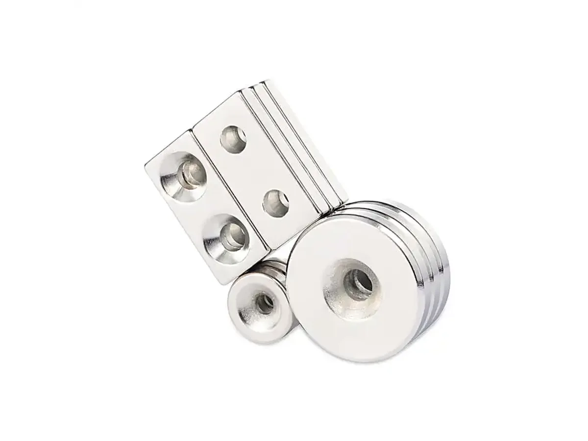
Un magnete al neodimio svasato è un magnete in NdFeB sinterizzato con un incavo conico attorno a un foro passante, che consente a una vite compatibile a testa svasata di posizionarsi a filo o quasi a filo con la superficie del magnete. Il foro risolve un’esigenza di fissaggio meccanico, ma comporta anche la rimozione di materiale magnetico e crea una sezione più sottile e fragile. Per questo motivo, OSENC considera la geometria del foro, la compatibilità con la vite e le dimensioni del corpo del magnete come elementi di un unico progetto, anziché aggiungere la svasatura in un secondo momento.
| Specifica | Opzioni di personalizzazione OSENC | Dati richiesti nel disegno tecnico |
|---|---|---|
| Materiale del magnete | Neodimio-ferro-boro sinterizzato (NdFeB) | Prestazioni magnetiche richieste o grado target |
| Gradi | Da N35 a N55, oltre ai gradi per alte temperature | Grado, temperatura di esercizio e requisiti magnetici |
| Definizione del foro | Diametro del foro passante + diametro maggiore della svasatura | Diametri esatti, non solo una designazione della vite come “M4” |
| Angolo di svasatura | Realizzato secondo l’angolo definito nel disegno | Angolo o disegno tecnico/norma della testa della vite |
| Posizione del foro | Al centro o nella posizione definita nel disegno | Linea d’asse, scostamenti e quote di posizione |
| Margine del corpo | Prima del rilascio del disegno alla produzione, OSENC valuta congiuntamente la distanza dal bordo, la profondità della svasatura, lo spessore finito e la sezione magnetica residua. I progetti che lasciano materiale insufficiente attorno alla svasatura vengono rivisti prima della formulazione del preventivo. | Dimensioni d’ingombro, diametro maggiore del foro, spessore e distanza dal bordo |
| Magnetizzazione | Specificato indipendentemente dalla svasatura | Direzione di magnetizzazione e requisito della faccia polare |
| Rivestimento | Scelto in base alle condizioni ambientali e ai requisiti del pezzo finito | Umidità, acqua, olio, contatto con sostanze chimiche, aspetto e condizioni di manipolazione |
Non definire il componente esclusivamente in base alla denominazione della vite. OSENC considera congiuntamente le dimensioni finite del magnete e l'interfaccia con la vite, affinché il foro sia adatto all'elemento di fissaggio senza sacrificare inutilmente materiale magnetico.
| Simbolo | Definizione | Dati da specificare |
|---|---|---|
| DE / L / La | Dimensioni del corpo del magnete | Diametro esterno finito o lunghezza × larghezza |
| T | Spessore finito | Spessore complessivo del magnete dopo il rivestimento |
| d | Diametro del foro passante | Diametro richiesto del foro di passaggio della vite |
| D | Diametro maggiore della svasatura | Diametro massimo dell'incavo conico |
| α | Angolo incluso della svasatura | Angolo o disegno tecnico/norma della testa della vite |
| X / Y | Posizione del centro del foro | Posizione del centro o distanze dai bordi di riferimento |
| e | Distanza dal bordo | Materiale residuo tra il bordo della svasatura e il bordo del magnete |
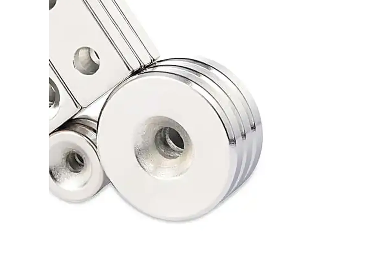
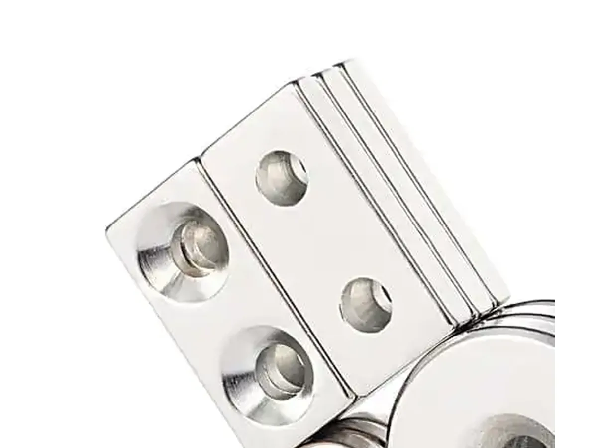
La sede svasata asporta NdFeB dal corpo finito; pertanto, una svasatura più ampia lascia una sezione magnetica inferiore rispetto a un magnete pieno con le stesse dimensioni esterne e lo stesso grado. La zona conica crea inoltre, attorno all’elemento di fissaggio, una sezione più sottile e più sensibile alle sollecitazioni.
OSENC valuta il foro e la svasatura in relazione all’intero corpo del magnete, per evitare di asportare inutilmente materiale dal circuito magnetico.
Adattiamo la geometria della svasatura alla testa della vite specificata, per ridurre il contatto non uniforme, i carichi d’urto e le sollecitazioni localizzate attorno alla sede.
Prima di approvare il disegno per la produzione, verifichiamo congiuntamente il materiale residuo, lo spessore finale e la profondità della svasatura.
OSENC produce corpi magnetici tondi, rettangolari e definiti da disegno, sulla base delle dimensioni finali. Valutiamo il foro in relazione all’intero corpo, anziché considerarlo una lavorazione meccanica isolata.
We define through-hole diameter, countersink major diameter, angle and hole position from the screw interface and approved assembly drawing.
We control grade, coating and magnetization direction together with the mechanical geometry so the finished part is released as one engineered component.
OSENC supplies countersunk neodymium magnets from N35 through N55, together with high-temperature grade types. We select the grade from the required magnetic output, operating temperature, magnet geometry and magnetic circuit rather than from grade number alone.
The countersunk feature does not determine polarity. Specify the required pole face or magnetization direction on the drawing so the finished mechanical geometry and magnetic orientation are correct together.
Sintered NdFeB also requires suitable surface protection. We select the coating from humidity, water, oil, chemical exposure, wear and appearance requirements, with particular attention to the countersunk edge and screw-contact area.
The countersunk face does not automatically define the magnetic pole. OSENC controls magnetization from the approved drawing so the mechanical mounting face and magnetic working face are not confused during production.
| Assemblaggio | What OSENC Needs Defined |
|---|---|
| Magnet to steel | Required working pole face and magnetization direction. |
| Magnet to magnet | Mating-face polarity so the two parts attract in the installed orientation. |
| Sensor or positioning assembly | Specified pole face and orientation relative to the sensing or locating component. |
An oversized recess removes unnecessary magnetic material and leaves a thinner section around the screw.
A mismatched angle creates uneven contact and concentrates stress around the countersunk edge.
Too little material between the recess and magnet edge increases chipping risk and reduces usable magnetic section.
The mechanical drawing can be correct while the magnetic orientation is wrong for the final assembly. Pole direction must be specified.
M3, M4 or M5 alone does not fully define clearance, head diameter or countersink angle. We use exact hole geometry.
The countersink must be reviewed against the finished magnet thickness so enough material remains below and around the recess.
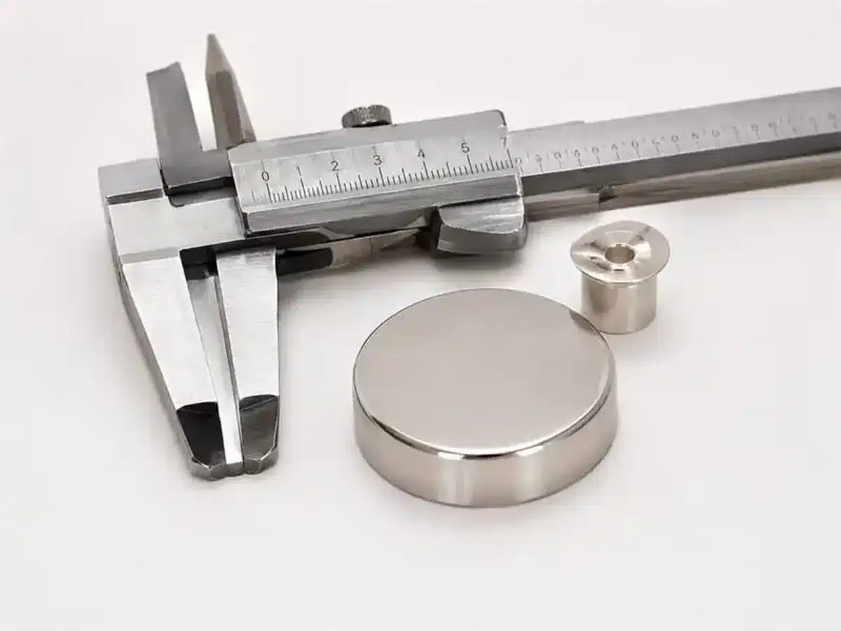
OSENC inspects the finished countersunk magnet against the approved drawing before shipment. The hole, countersink, body dimensions, edge condition and magnetization requirement are checked as features of one finished part, not as unrelated inspection items.
| Applicazione | Why a Countersunk Magnet Fits | Define Before RFQ |
|---|---|---|
| Fixtures & Jigs | Flush screw mounting provides removable mechanical retention without relying on adhesive. | Working face, screw geometry, mounting surface and required magnetic function. |
| Access Panels & Covers | Low-profile screw mounting supports serviceable panels and repeatable installation. | Air gap, mating steel or magnet, polarity and available installation thickness. |
| Furniture & Cabinet Hardware | Concealed or flush retention can be integrated into a bracket, panel or frame. | Available envelope, screw head, coating environment and mating component. |
| Display & Signage Systems | Mechanical fixing keeps the magnet position repeatable when panels are removed and reinstalled. | Panel thickness, pull direction, mounting pattern and working face. |
| Sensor & Positioning Assemblies | Drawing-controlled hole position helps locate the magnetic element relative to another component. | Pole face, sensor orientation, gap and positional dimensions. |
| OEM Mechanical Assemblies | Hole geometry, coating and magnetization can be defined together with the mating hardware. | 2D/3D drawing, screw interface, environment and assembly orientation. |
| Use Countersunk NdFeB When | Use Another Mounting Route When |
|---|---|
| You need a removable or mechanically retained magnet fixed by a screw. | The magnet is extremely thin and the required countersink would leave too little material. |
| The screw head must sit flush or below the working surface. | The assembly load puts high clamping force directly through the brittle magnet. |
| Adhesive bonding is unsuitable for the substrate, environment or service method. | You need maximum magnetic cross-section from a fixed outer envelope and the hole is not essential. |
| Hole position can be controlled from a drawing and aligned with a mating bracket, panel or fixture. | The actual requirement is a shaft/pass-through hole, threaded steel cup, pot magnet or another mechanical interface. |
For a plain center hole without a tapered screw seat, review magneti al neodimio ad anello. For a steel-cased holding assembly with a mounting feature, review magneti a tazza. If you are considering drilling a finished magnet yourself, read È possibile forare i magneti al neodimio? before changing the part.
Give OSENC the assembly inputs once. We use them to review the magnet body, screw interface and magnetic orientation together before quotation.
Send the finished magnet dimensions, through-hole diameter d, countersink major diameter D, countersink angle α, hole position, critical tolerances and the screw-head drawing or dimensions when available.
Use the screw designation as a reference, but send the actual clearance diameter, screw-head diameter and countersink angle. OSENC defines the hole from the real screw interface instead of assuming one geometry from the thread size alone.
Yes. The recess removes NdFeB material, so the finished part has less magnetic cross-section than a solid magnet with the same outer dimensions and grade. We review the countersink together with the body size and magnetic requirement.
Sintered NdFeB is hard and brittle. Excessive tightening, a mismatched screw-head angle, impact, poor seating or insufficient material around the recess can create concentrated stress. The screw should seat correctly and should not be overtightened.
We review edge distance together with countersink diameter, countersink depth, finished thickness and the remaining magnetic section. If the geometry leaves insufficient material around the recess, we revise the part before quotation or production release instead of applying one generic edge-margin number to every design.
We define hole position and magnetization from the approved product drawing. Send the centerline or X/Y offsets together with the required pole face or magnetization direction so the mechanical and magnetic orientations are controlled together.
Specify opposite mating-face poles so the two installed magnets attract. Mark the required countersunk-face polarity or magnetization direction on the drawing; OSENC controls polarity from that requirement rather than assuming it from the hole location.
Send the finished magnet dimensions, hole diameter, countersink major diameter, angle, position, grade or magnetic target, magnetization, coating, operating condition and quantity. OSENC reviews the screw interface, remaining magnetic section and magnetic orientation together, then quotes the part to the approved drawing.