







OSENC produkuje według rysunku magnesy neodymowe z otworem stożkowym do zespołów montowanych śrubami, w wersjach okrągłych, prostokątnych oraz o geometrii określonej na rysunku. Korpus magnesu, otwór przelotowy, średnica, kąt i położenie pogłębienia stożkowego, powłoka oraz sposób magnesowania są kontrolowane jako parametry jednego gotowego elementu. Prosimy przesłać rysunek magnesu lub wymiary łba śruby. Przed zatwierdzeniem do produkcji nasz zespół inżynierów sprawdzi dopasowanie śruby, pozostały przekrój materiału magnetycznego oraz możliwość wykonania.
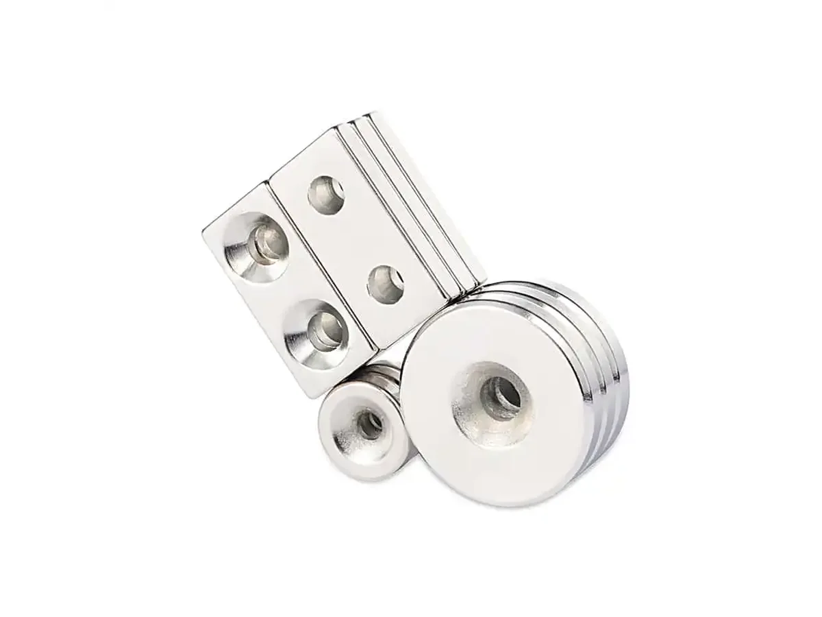
Magnes neodymowy z otworem stożkowym to spiekany magnes NdFeB z otworem przelotowym otoczonym stożkowym pogłębieniem, w którym odpowiednio dopasowany wkręt z łbem płaskim może licować lub niemal licować z powierzchnią magnesu. Otwór umożliwia montaż mechaniczny, ale jednocześnie zmniejsza ilość materiału magnetycznego i tworzy cieńszy, bardziej kruchy przekrój. Dlatego OSENC uwzględnia geometrię otworu, dopasowanie wkrętu i wymiary korpusu magnesu w jednym projekcie, zamiast dodawać pogłębienie stożkowe na późniejszym etapie.
| Specyfikacja | Opcje niestandardowe OSENC | Wymagane dane na rysunku |
|---|---|---|
| Materiał magnetyczny | Spiekany materiał neodymowo-żelazowo-borowy (NdFeB) | Wymagane parametry magnetyczne lub docelowa klasa |
| Klasy | N35–N55 oraz klasy wysokotemperaturowe | Klasa, temperatura pracy i wymagania magnetyczne |
| Definicja otworu | Średnica otworu przelotowego + większa średnica pogłębienia stożkowego | Dokładne średnice, nie tylko oznaczenie śruby, takie jak “M4” |
| Kąt pogłębienia stożkowego | Wykonanie zgodnie z kątem określonym na rysunku | Kąt lub rysunek/norma łba śruby |
| Położenie otworu | Centralnie lub w położeniu określonym na rysunku | Linia środkowa, odsunięcia i wymiary położenia |
| Margines materiału korpusu | Przed zatwierdzeniem rysunku do produkcji OSENC łącznie weryfikuje odległość od krawędzi, głębokość pogłębienia stożkowego, grubość wyrobu gotowego oraz pozostały przekrój materiału magnetycznego. Projekty, w których wokół pogłębienia stożkowego pozostaje zbyt mało materiału, są korygowane przed wyceną. | Wymiary gabarytowe, większa średnica otworu, grubość i odległość od krawędzi |
| Magnesowanie | Określane niezależnie od pogłębienia stożkowego | Kierunek magnesowania i wymagania dotyczące powierzchni biegunowej |
| Powłoka | Dobór zależny od środowiska i wymagań wobec gotowego elementu | Wilgoć, woda, olej, kontakt z chemikaliami, wygląd i warunki obchodzenia się z elementem |
Nie należy definiować części wyłącznie na podstawie oznaczenia śruby. OSENC uwzględnia zarówno wymiary gotowego magnesu, jak i geometrię współpracy ze śrubą, aby otwór był dopasowany do elementu złącznego bez niepotrzebnego zmniejszania ilości materiału magnetycznego.
| Symbol | Definicja | Co należy określić |
|---|---|---|
| Śr. zewn. / Dł. / Szer. | Wymiary korpusu magnesu | Gotowa średnica zewnętrzna lub długość × szerokość |
| T | Grubość gotowego elementu | Całkowita grubość magnesu po nałożeniu powłoki |
| d | Średnica otworu przelotowego | Wymagana średnica otworu przelotowego pod śrubę |
| D | Większa średnica pogłębienia stożkowego | Maksymalna średnica stożkowego zagłębienia |
| α | Kąt rozwarcia pogłębienia stożkowego | Kąt lub rysunek/norma łba śruby |
| X / Y | Położenie środka otworu | Położenie środka lub odległości od krawędzi bazowych |
| e | Odległość od krawędzi | Pozostały materiał między krawędzią pogłębienia a krawędzią magnesu |
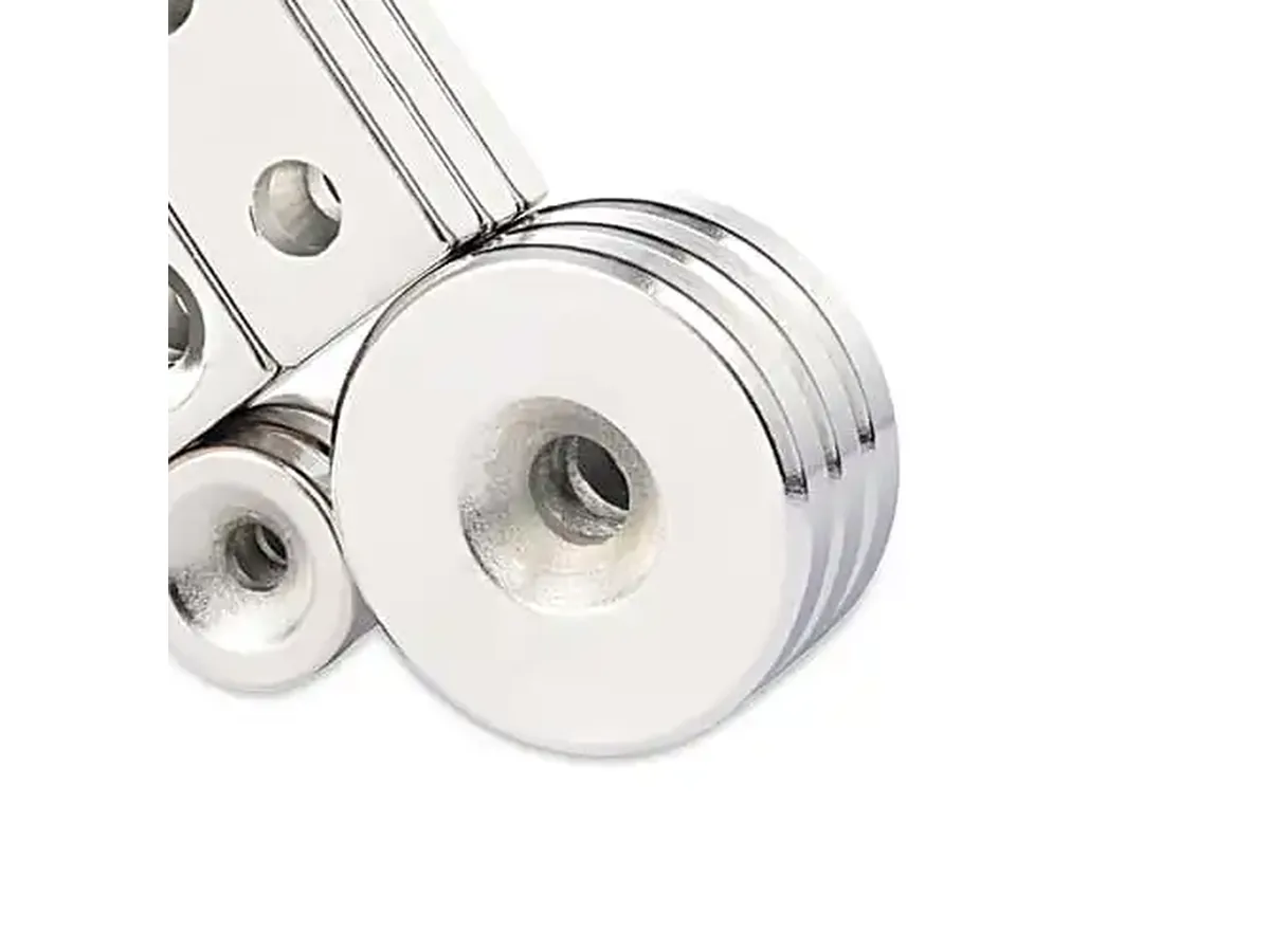
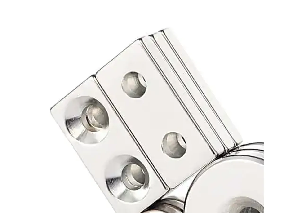
The countersunk recess removes NdFeB from the finished body, so a larger recess leaves less magnetic cross-section than a solid magnet with the same outer dimensions and grade. The tapered area also creates a thinner, more stress-sensitive section around the fastener.
OSENC reviews the hole and countersink against the complete magnet body so unnecessary material is not removed from the magnetic circuit.
We match the countersink geometry to the specified screw head to reduce uneven contact, impact loading and localized stress around the recess.
We check remaining material, finished thickness and countersink depth together before the drawing is released for production.
OSENC produces round, rectangular and drawing-defined magnet bodies from finished dimensions. We review the hole against the complete body rather than treating it as an isolated machining feature.
We define through-hole diameter, countersink major diameter, angle and hole position from the screw interface and approved assembly drawing.
We control grade, coating and magnetization direction together with the mechanical geometry so the finished part is released as one engineered component.
OSENC supplies countersunk neodymium magnets from N35 through N55, together with high-temperature grade types. We select the grade from the required magnetic output, operating temperature, magnet geometry and magnetic circuit rather than from grade number alone.
The countersunk feature does not determine polarity. Specify the required pole face or magnetization direction on the drawing so the finished mechanical geometry and magnetic orientation are correct together.
Sintered NdFeB also requires suitable surface protection. We select the coating from humidity, water, oil, chemical exposure, wear and appearance requirements, with particular attention to the countersunk edge and screw-contact area.
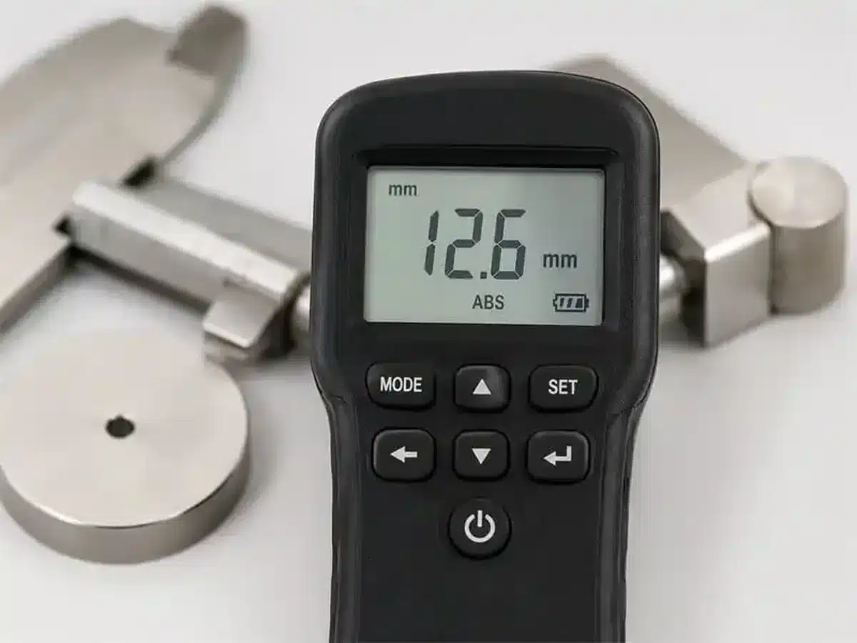
The countersunk face does not automatically define the magnetic pole. OSENC controls magnetization from the approved drawing so the mechanical mounting face and magnetic working face are not confused during production.
| Montaż | What OSENC Needs Defined |
|---|---|
| Magnet to steel | Required working pole face and magnetization direction. |
| Magnet to magnet | Mating-face polarity so the two parts attract in the installed orientation. |
| Sensor or positioning assembly | Specified pole face and orientation relative to the sensing or locating component. |
An oversized recess removes unnecessary magnetic material and leaves a thinner section around the screw.
A mismatched angle creates uneven contact and concentrates stress around the countersunk edge.
Too little material between the recess and magnet edge increases chipping risk and reduces usable magnetic section.
The mechanical drawing can be correct while the magnetic orientation is wrong for the final assembly. Pole direction must be specified.
M3, M4 or M5 alone does not fully define clearance, head diameter or countersink angle. We use exact hole geometry.
The countersink must be reviewed against the finished magnet thickness so enough material remains below and around the recess.
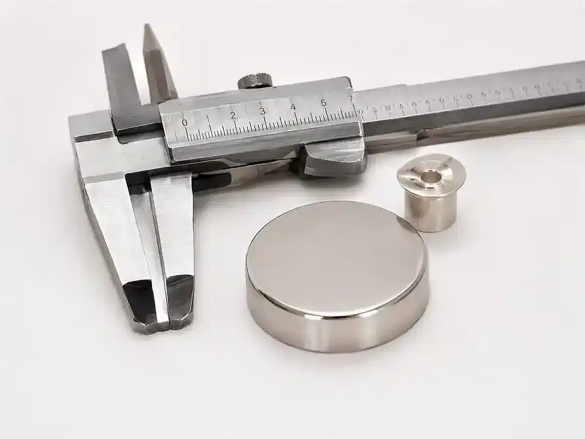
OSENC inspects the finished countersunk magnet against the approved drawing before shipment. The hole, countersink, body dimensions, edge condition and magnetization requirement are checked as features of one finished part, not as unrelated inspection items.
| Zastosowanie | Why a Countersunk Magnet Fits | Define Before RFQ |
|---|---|---|
| Fixtures & Jigs | Flush screw mounting provides removable mechanical retention without relying on adhesive. | Working face, screw geometry, mounting surface and required magnetic function. |
| Access Panels & Covers | Low-profile screw mounting supports serviceable panels and repeatable installation. | Air gap, mating steel or magnet, polarity and available installation thickness. |
| Furniture & Cabinet Hardware | Concealed or flush retention can be integrated into a bracket, panel or frame. | Available envelope, screw head, coating environment and mating component. |
| Display & Signage Systems | Mechanical fixing keeps the magnet position repeatable when panels are removed and reinstalled. | Panel thickness, pull direction, mounting pattern and working face. |
| Sensor & Positioning Assemblies | Drawing-controlled hole position helps locate the magnetic element relative to another component. | Pole face, sensor orientation, gap and positional dimensions. |
| OEM Mechanical Assemblies | Hole geometry, coating and magnetization can be defined together with the mating hardware. | 2D/3D drawing, screw interface, environment and assembly orientation. |
| Use Countersunk NdFeB When | Use Another Mounting Route When |
|---|---|
| You need a removable or mechanically retained magnet fixed by a screw. | The magnet is extremely thin and the required countersink would leave too little material. |
| The screw head must sit flush or below the working surface. | The assembly load puts high clamping force directly through the brittle magnet. |
| Adhesive bonding is unsuitable for the substrate, environment or service method. | You need maximum magnetic cross-section from a fixed outer envelope and the hole is not essential. |
| Hole position can be controlled from a drawing and aligned with a mating bracket, panel or fixture. | The actual requirement is a shaft/pass-through hole, threaded steel cup, pot magnet or another mechanical interface. |
For a plain center hole without a tapered screw seat, review neodymium ring magnets. For a steel-cased holding assembly with a mounting feature, review magnesy garnkowe. If you are considering drilling a finished magnet yourself, read Czy można wiercić w magnesach neodymowych? before changing the part.
Give OSENC the assembly inputs once. We use them to review the magnet body, screw interface and magnetic orientation together before quotation.
Send the finished magnet dimensions, through-hole diameter d, countersink major diameter D, countersink angle α, hole position, critical tolerances and the screw-head drawing or dimensions when available.
Use the screw designation as a reference, but send the actual clearance diameter, screw-head diameter and countersink angle. OSENC defines the hole from the real screw interface instead of assuming one geometry from the thread size alone.
Yes. The recess removes NdFeB material, so the finished part has less magnetic cross-section than a solid magnet with the same outer dimensions and grade. We review the countersink together with the body size and magnetic requirement.
Sintered NdFeB is hard and brittle. Excessive tightening, a mismatched screw-head angle, impact, poor seating or insufficient material around the recess can create concentrated stress. The screw should seat correctly and should not be overtightened.
We review edge distance together with countersink diameter, countersink depth, finished thickness and the remaining magnetic section. If the geometry leaves insufficient material around the recess, we revise the part before quotation or production release instead of applying one generic edge-margin number to every design.
We define hole position and magnetization from the approved product drawing. Send the centerline or X/Y offsets together with the required pole face or magnetization direction so the mechanical and magnetic orientations are controlled together.
Specify opposite mating-face poles so the two installed magnets attract. Mark the required countersunk-face polarity or magnetization direction on the drawing; OSENC controls polarity from that requirement rather than assuming it from the hole location.
Send the finished magnet dimensions, hole diameter, countersink major diameter, angle, position, grade or magnetic target, magnetization, coating, operating condition and quantity. OSENC reviews the screw interface, remaining magnetic section and magnetic orientation together, then quotes the part to the approved drawing.