







Microphone Magnet Selection
Osenc helps B2B buyers review custom neodymium magnet requirements for microphone components before sampling, including drawings, samples, dimensions, coating, magnetization direction, working gap and inspection needs.
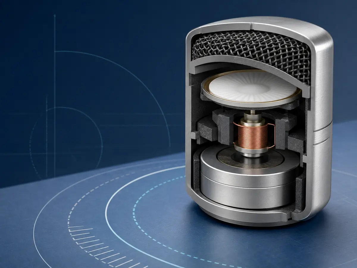
Application Boundary
This page is for OEM microphone components and audio assemblies where the magnet works inside the device. It does not cover magnetic microphone mounts, clips, stand accessories or speaker magnet selection.
Small neodymium magnets used near a diaphragm, voice coil, pole piece or compact microphone magnetic circuit.
Shape, size, tolerance, coating, magnetization direction, working gap, sample check and inspection method.
Exact grade, dimensions, field target, material choice and test method must be confirmed from the application conditions.
Magnetic Circuit
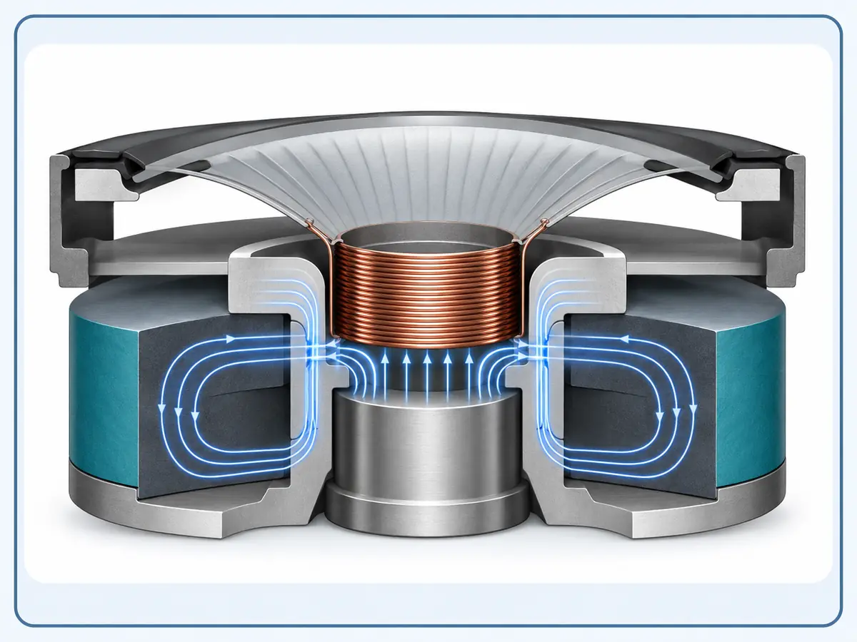
In a simplified dynamic microphone structure, the diaphragm and voice coil move within a magnetic field produced by a permanent magnet and pole structure. For a magnet buyer, the practical question is not only whether neodymium is strong enough. The question is whether the magnet geometry, direction and assembly clearance support the intended magnetic circuit.
A small change in coating thickness, tolerance stack-up or magnetization direction can affect the working gap and final assembly fit. That is why Osenc treats microphone magnet selection as a drawing and application review task, not only a catalog-size matching task.
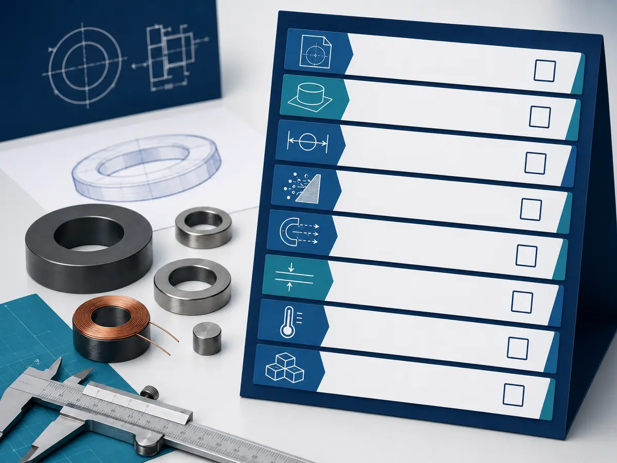
Evidence note: The images on this page are conceptual visuals and simplified diagrams. They are not customer drawings, Osenc microphone case photos or measured test records.
Selection Factors
For custom magnets for microphones, the best starting point is a controlled specification review. The table below shows the main variables Osenc asks buyers to confirm before quotation or sampling.
| Selection factor | Why it matters | What to send for RFQ review |
|---|---|---|
| Size and shape | Microphone components often have limited internal space and tight assembly clearance. | Drawing, 3D file, sample photo or target outside and inside dimensions. |
| Tolerance | Tolerance stack-up can change the coil clearance, seating position and working gap. | Critical dimensions, tolerance class and assembly contact surfaces. |
| Magnetization direction | The magnet direction must match the pole layout and useful magnetic circuit. | Axial, diametrical, radial or custom direction requirement if known. |
| Working gap | Air gap affects the useful field inside the microphone structure. | Gap distance, pole piece structure and nearby magnetic or non-magnetic materials. |
| Coating | Coating affects corrosion resistance and final dimensions. | Environment, coating preference and whether coating thickness is critical. |
| Inspection | Pull force or surface field alone may not represent microphone performance. | Required inspection method, sample approval rule and critical acceptance points. |
Magnet Options
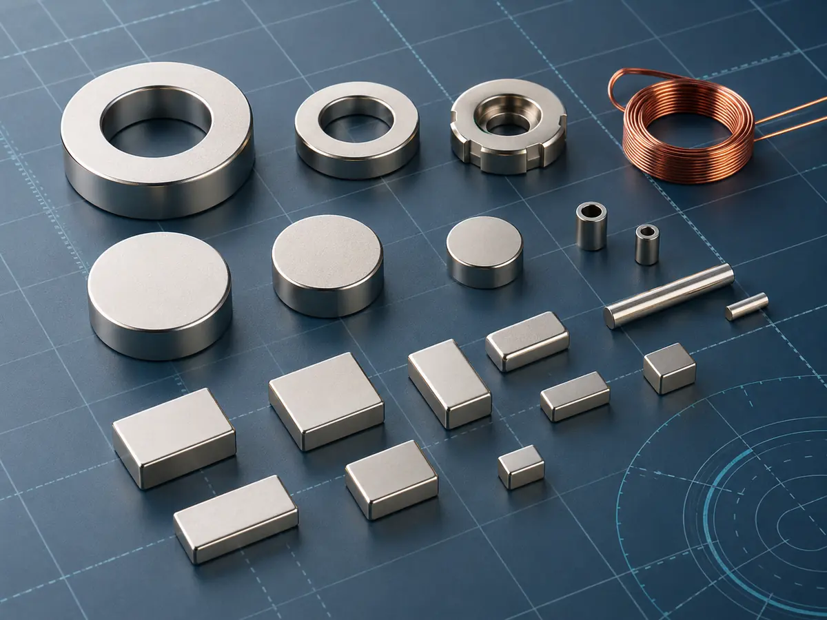
Microphone magnet projects may use small ring magnets, disc magnets, short rods, compact blocks or custom micro magnet shapes. The suitable form depends on the magnetic circuit, assembly space, pole structure and target inspection method.
Osenc can review requirements through micro magnets, neodymium ring magnets, neodymium disc magnets and other neodymium magnet capabilities. Final feasibility depends on geometry, coating, tolerance, handling and manufacturability.
Material note: NdFeB is often considered where compact size and strong magnetic field are required. Other magnet materials may be reviewed only when the temperature, corrosion, demagnetization or cost conditions justify them.
Decision Risks
The safest selection process avoids one-variable decisions. A high grade or strong pull reading does not automatically mean the magnet is right for a microphone component.
Higher grade may not solve a geometry, temperature, coating or demagnetization issue. Grade should be reviewed with the whole structure.
Wrong magnetization can make an otherwise correct-looking part unsuitable for the intended magnetic circuit.
Coating can change final dimensions and assembly clearance, especially in compact microphone components.
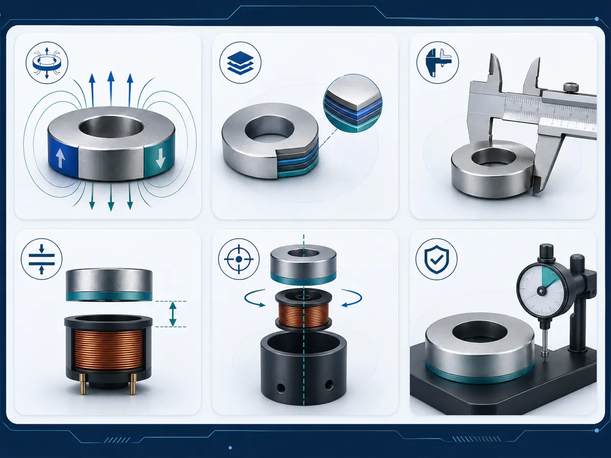
Performance boundary: Pull force and surface field can support inspection, but they should not be presented as complete proof of microphone acoustic performance. The useful test method depends on the final microphone structure and buyer acceptance requirements.
Engineering Review
Osenc reviews microphone magnet requirements before sampling so the buyer can reduce unclear specifications and avoid avoidable sample iterations.
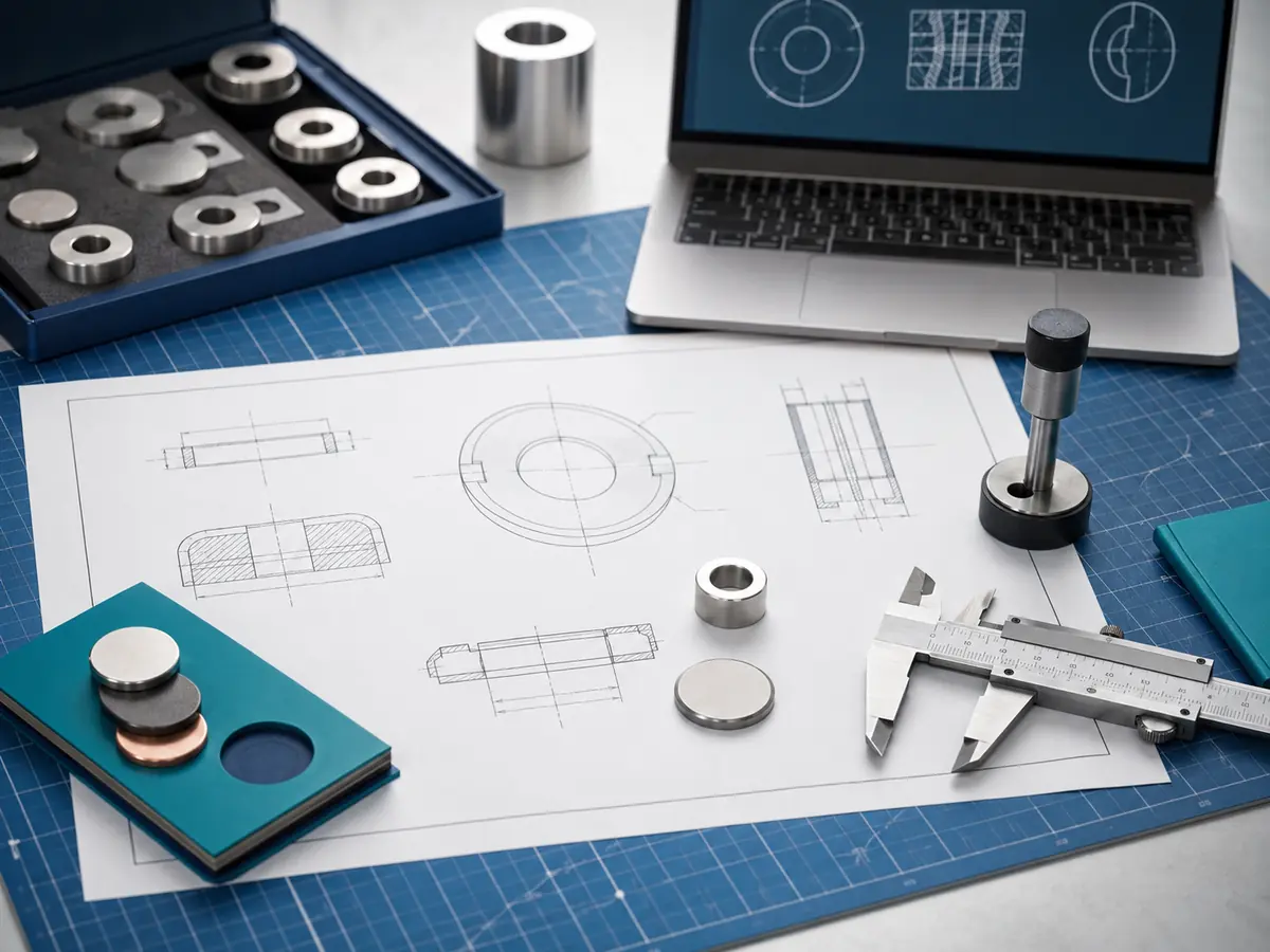
Confirm whether the request is for an internal microphone component, magnetic circuit or unrelated mount accessory.
Review size, tolerance, coating, magnetization direction, working gap and assembly method.
Define sample quantity, inspection point and acceptance requirement before trial production.
Prepare clearer quotation inputs for custom magnet manufacturing and project communication.
RFQ Checklist
For faster review, send the information below with your inquiry. If some details are not available, Osenc can start from the drawing, sample photo and application description.
Related Osenc Capabilities
These confirmed Osenc pages help buyers prepare a better custom magnet inquiry.
Drawing-based custom magnet review and sampling support.
Micro MagnetsSmall and ultra-small magnet feasibility review.
Neodymium Magnet CoatingCoating options and corrosion protection considerations.
Quality ManagementInspection and quality-control context for custom magnet projects.
FAQ
Neodymium magnets may be used in compact microphone components where a strong magnetic field is required in limited space. The final design still depends on the microphone structure, working gap, magnetization direction and assembly method.
No. N52 can be useful in some compact designs, but grade should be selected with temperature, geometry, cost, coating, working gap and demagnetization risk in mind.
No. Pull force and surface field can support magnet inspection, but they do not fully represent microphone acoustic performance. The correct acceptance method depends on the final assembly and buyer test requirement.
Osenc can review micro magnet and custom neodymium magnet requirements. Final manufacturability depends on geometry, tolerance, coating, handling, magnetization and inspection requirements.
No. This page is about internal microphone component magnets. Magnetic mounts, clips and stand accessories have a different selection intent and are outside the page scope.
Osenc can review custom microphone magnet requirements including shape, tolerance, coating, magnetization direction, working gap, sample rule and RFQ details before production discussion.