







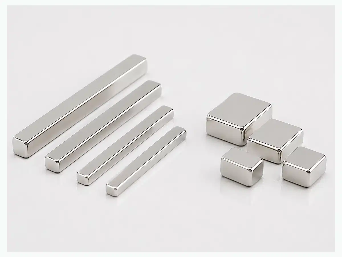
We manufacture custom sintered NdFeB bar magnets for OEM assemblies where a long, narrow magnetic footprint is required. Your approved drawing sets the dimensions, tolerance, pole direction, coating and inspection requirements, while grade selection is matched to the magnetic target and operating conditions. Send your L × W × H, tolerance, magnetization, temperature and quantity for quotation.
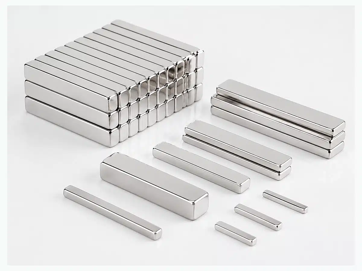
We quote bar magnets in metric dimensions. The ranges below show the current capability for this product family; the approved drawing then becomes the production reference for the final geometry, tolerance, coating and magnetization.
| Specification | OSENC Capability | Production Reference |
|---|---|---|
| Length | 1–254 mm | Finished length and tolerance |
| Width | 0.5–127 mm | Installation width and edge clearance |
| Height | 0.3–120 mm | Thickness / height and pole direction |
| Largest bar in current capability range | 254 × 80 × 50 mm | Full geometry, tolerance and magnetization are locked on the approved drawing |
| Smallest bar in current capability range | 1 × 1 × 0.3 mm | Handling, coating and tolerance requirements are defined before production |
| Tolerance | ±0.10 mm quotation reference; ±0.05 mm available on approved critical dimensions | Final tolerance is dimension-specific and locked on the approved drawing |
| Standard grades | N35 / N38 / N40 / N42 / N45 / N48 / N50 / N52 / N54 / N55 | Magnetic target, geometry and operating temperature |
| High-temperature families | M / H / SH / UH / EH / AH | Exact grade suffix and demagnetization condition |
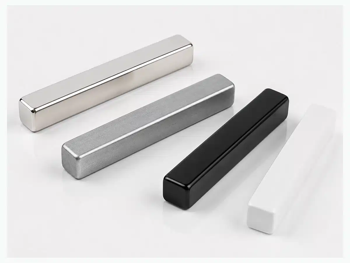
| Standard coating | Ni-Cu-Ni | Environment and allowable coating build-up |
| Optional coatings | Zinc / Epoxy / Ni-Cu-Ni + Epoxy / Parylene / Phosphate / Gold / PTFE | Humidity, water, chemical or wear exposure |
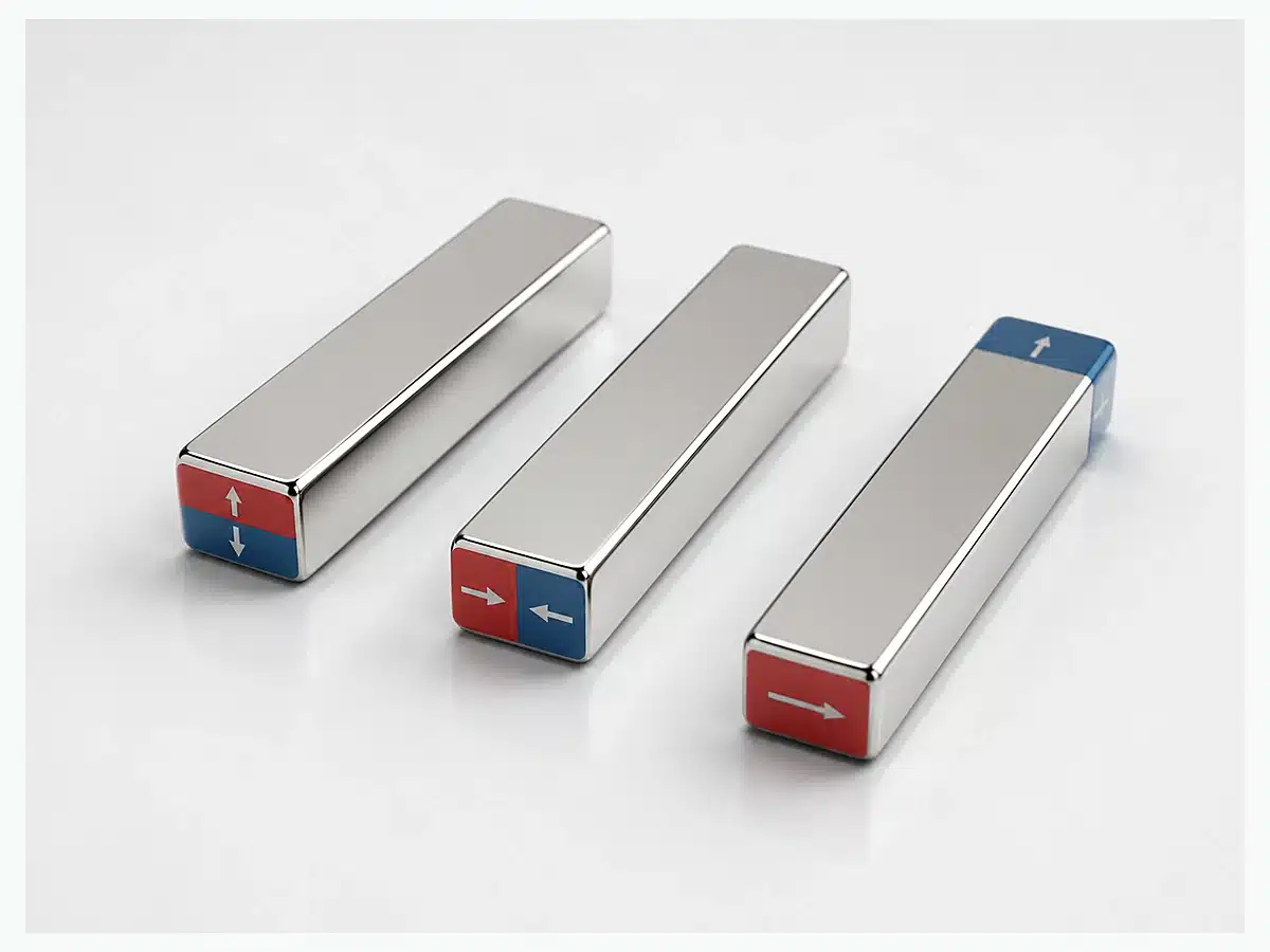
| Magnetization | Through thickness standard; through width / through length available for drawing-defined projects | Pole direction and any multipole layout are controlled by the approved pole drawing |
We start with the space available in your assembly and the magnetic job the part needs to do. From there, we set the dimensions, pole direction, coating and inspection requirements, then match the grade to the real magnetic circuit and operating conditions.
| Specification Item | Our Starting Point | What Goes on the Order |
|---|---|---|
| Geometry | Length × Width × Height | Show holes, countersinks, slots, steps, radii or custom ends on the drawing |
| Tolerance | ±0.10 mm quotation reference | Critical dimensions can be specified to ±0.05 mm after drawing approval; tighter values require dimension-specific approval |
| Grade | N35–N55 range | Use M / H / SH / UH / EH / AH families when temperature or demagnetization resistance drives selection |
| Magnetization | Through thickness | Through-width, through-length and defined multipole layouts are produced to the approved pole drawing |
| Coating | Ni-Cu-Ni | Epoxy, Parylene, PTFE and other available systems are matched to humidity, water, chemical and wear exposure |
| Magnetic acceptance | Grade + approved geometry | Gauss, flux or pull-force targets are tied to a defined and reproducible test condition |
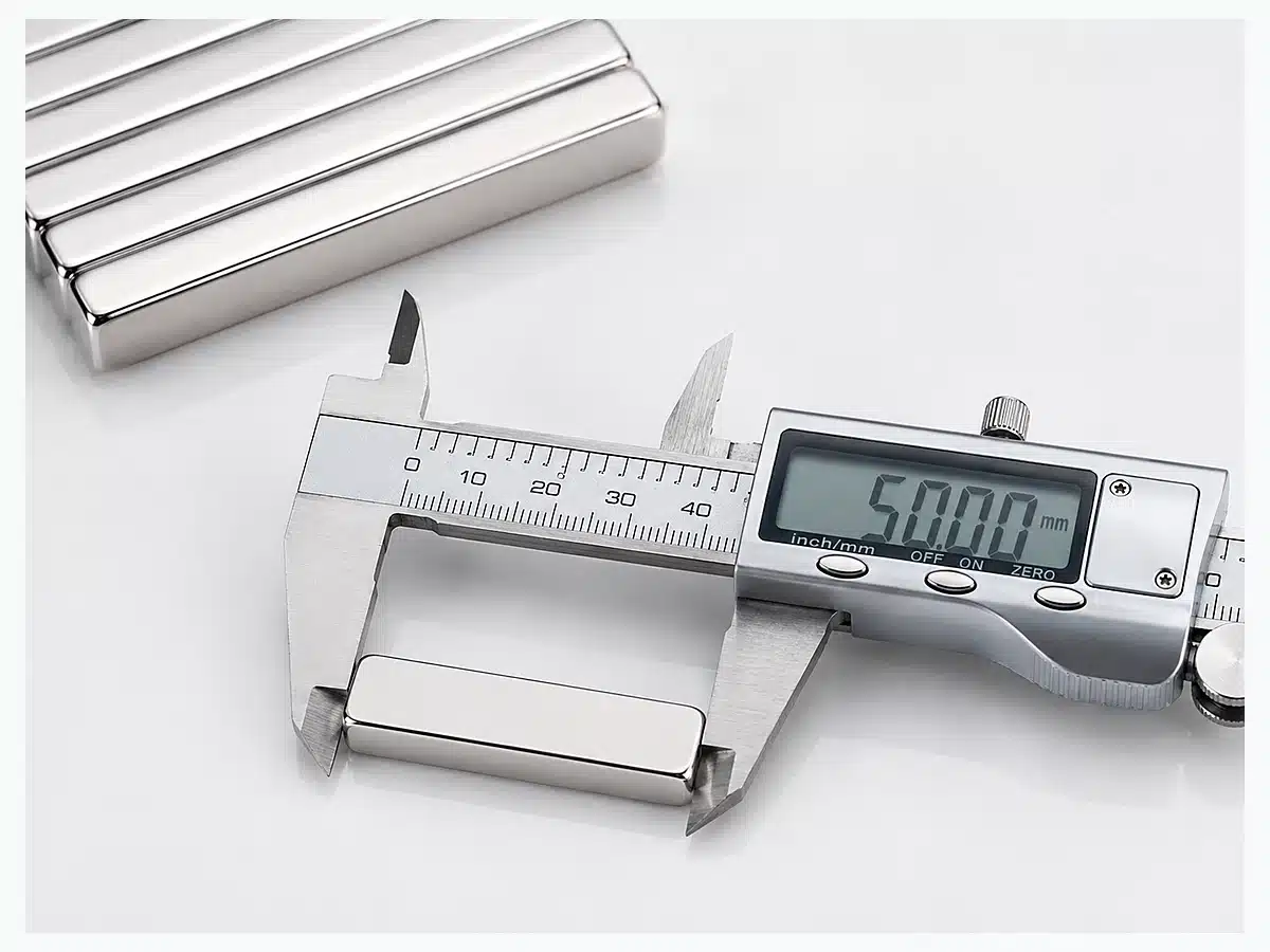
OSENC uses Length × Width × Height for page notation. For example, 90 × 3 × 2 mm means 90 mm long, 3 mm wide and 2 mm high. Pole direction should be shown separately instead of inferred from the size alone.
Final dimensions and tolerances follow the approved drawing.
Example: 90 × 3 × 2 mm = 90 mm × 3 mm × 2 mm.
Through-thickness magnetization is the standard direction for this product family. Through-width, through-length and defined multipole layouts are also available when they are clearly shown on the pole drawing.
L × W × H
Use drawing notes for chamfer, edge break and critical dimensions.
Define hole diameter, position and remaining edge material. Very small holes increase machining and fracture risk.
We manufacture countersinks, slots, steps, radii and custom ends when the complete feature geometry is shown on the drawing.
Use this product family when the magnet is clearly elongated and its length follows a rail, channel, housing, sensing path or linear assembly. More balanced rectangular or square geometries belong in our neodymium block magnet range.
The available installation space is elongated and the magnet needs to follow that geometry.
Length is not the defining dimension and the part behaves more like a conventional rectangular or square block.
The correct outer size with the wrong magnetization is still the wrong part. Put pole direction on the drawing.
Grade matters, but it is only one part of the result. Geometry, pole direction, air gap and temperature all affect how much useful magnetic performance reaches the assembly, so we size the magnet around the complete working condition rather than the N-number alone.
Length, cross-section and aspect ratio change the magnetic circuit and demagnetizing condition.
Through-thickness, width or length changes the pole faces presented to the assembly.
Adhesive, plastic walls, paint, coating and assembly clearance can reduce usable magnetic interaction.
Normal and maximum operating temperature influence grade-family selection and demagnetization margin.
The values below are grade-family guidelines. We select the final grade from the magnet geometry, reverse field, operating temperature and the complete magnetic circuit.
| Grade Family | Typical Maximum Working Temperature | How We Choose |
|---|---|---|
| Nxx | 80°C | Exact grade matched to geometry and magnetic circuit |
| NxxM | 100°C | Specific M grade selected for the operating condition |
| NxxH | 120°C | Working and maximum temperature included in grade selection |
| NxxSH | 150°C | Selected with demagnetizing conditions included |
| NxxUH | 180°C | Selected against the complete magnetic circuit |
| NxxEH | 200°C | Selected against the complete magnetic circuit |
| NxxAH | 230°C | Selected against the complete magnetic circuit |
Ni-Cu-Ni is our standard finish for dry indoor use. For humidity, water, chemicals or wear, we match the coating system to the actual service environment instead of treating one coating as a universal answer.
| Environment | Our Coating Direction | What Goes on the Order |
|---|---|---|
| Normal indoor / dry | Ni-Cu-Ni | Any critical coating thickness or appearance criteria |
| General industrial | Ni-Cu-Ni | Wear, handling and exposure |
| Humid environment | Epoxy / Ni-Cu-Ni + Epoxy | Moisture exposure and edge protection |
| Higher corrosion concern | Parylene | Actual service exposure |
| Water exposure | Parylene / PTFE | Immersion, splash or intermittent exposure |
| Outdoor | Epoxy / Parylene | Weather exposure and required validation |
| Salt / marine | Project-specific coating | Required corrosion test standard and acceptance criteria |
| Acid / alkali | Project-specific coating selection | Chemical, concentration, temperature and exposure time |
Simple rectangular bars with a standard coating and clear pole direction are straightforward to manufacture. Very thin, very long or heavily machined parts need more attention because NdFeB is hard and brittle, so we check the geometry before the drawing is released for production.
| Design Situation | What We Check | Why It Matters |
|---|---|---|
| Very thin cross-sections | Handling, grinding, coating and edge condition | Thin sintered NdFeB parts are easier to chip or crack |
| Long or high-aspect-ratio bars | Straightness, handling and magnetization route | Long, slender parts need tighter process handling |
| Magnetization through the long direction | Magnetizing feasibility and pole definition | A long magnetization path changes the magnetizing requirement |
| Small holes or thin remaining walls | Feature position, remaining material and machining risk | Local stress raises the risk of chips and cracks |
| Multiple holes, slots or stepped features | Feature spacing and remaining cross-section | Complex machining reduces the amount of supporting material |
| Large cross-sections or unusual combinations of dimensions | Handling, coating, magnetization and safe assembly | The complete geometry matters more than any single dimension |
Bar geometry works best when a long, narrow magnet follows the magnetic path, sensing path or available installation space better than a conventional block. We then match the pole direction, working gap, temperature and mechanical protection to that application.
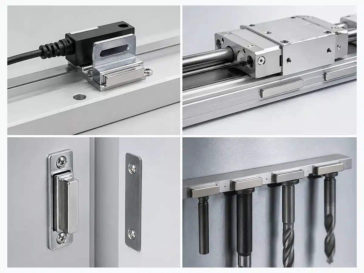
Why it fits: follows a longer sensing path or narrow housing.
Key design inputs: pole direction, working gap and sensor position.
Why it fits: fits an elongated magnetic-circuit segment.
Key design inputs: geometry, grade, operating temperature and pole orientation.
Why it fits: aligns with the direction of linear motion.
Key design inputs: magnet spacing, pole layout, air gap and moving envelope.
Why it fits: follows a long contact or closure area.
Key design inputs: mating steel, contact area, air gap and required retention.
Why it fits: distributes holding or locating force along a narrow rail or fixture.
Key design inputs: steel contact, air gap, cover thickness, impact protection and required holding force.
Why it fits: bar magnets can be built into rails, housings and repeated magnetic circuits.
Key design inputs: complete assembly geometry, pole layout, steel circuit, working gap and protection method.
We keep the important details tied to one approved specification: geometry, tolerance, pole direction, coating, magnetic acceptance and packaging. That makes the move from sample to repeat production much cleaner and gives your purchasing and engineering teams one reference to work from.
Critical L × W × H dimensions, tolerances and machined features follow the approved drawing.
Pole direction is shown on the drawing, so production and assembly teams are working from the same orientation.
When Gauss, flux or pull force is specified, the test condition is defined with the target so repeat orders are judged the same way.
The coating system is selected around humidity, water, chemicals, wear and the finished-dimension requirement.
The approved drawing and inspection points stay with the part as the reference for repeat production.
Polarity arrangement, spacing and protection are set around the magnet strength, geometry and handling needs.
We support custom prototypes and small trial quantities for new designs. Once the drawing, fit and inspection targets are approved, the same specification becomes the reference for repeat production.
Send Your Drawing to OSENC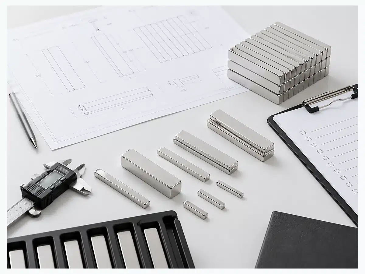
Our workflow follows the approved drawing, agreed inspection points and order-specific packaging requirements.
Send as many of these inputs as you have. We use them to remove guesswork, define the magnet clearly and quote against the same requirements your engineering team expects.
Send the available installation space, what the magnet needs to attract or sense, the working gap, temperature and expected quantity. We can start the configuration from those inputs before the final drawing is complete.
Send Application RequirementsOSENC manufactures within a current capability range of 1–254 mm in length, 0.5–127 mm in width and 0.3–120 mm in height. The largest bar shown in this capability range is 254 × 80 × 50 mm and the smallest is 1 × 1 × 0.3 mm. Final three-dimensional geometry is controlled by the approved drawing.
OSENC uses ±0.10 mm as the quotation reference tolerance, with ±0.05 mm available on approved critical dimensions. Tighter requirements are handled dimension by dimension on the production drawing.
Not automatically. OSENC selects grade together with geometry, pole direction, air gap, mating material, temperature and demagnetizing conditions. The required assembly performance determines the grade family, not the N-number alone.
Show the pole direction on your drawing. Through-thickness is the standard direction, while through-width, through-length and defined multipole layouts are produced for drawing-defined projects.
Yes. OSENC quotes numerical pull-force or surface-Gauss acceptance when the part and test condition are defined. Pull-force specifications include mating steel, thickness, contact condition and pull direction; Gauss specifications include probe position and orientation.
Yes. OSENC produces drawing-defined round holes, countersinks, slots, steps, radii and custom end features. Very small holes and thin remaining walls receive tighter machining and breakage control.
Yes. OSENC quotes custom prototypes and small trial quantities. For new applications, sample validation locks fit, magnetic output, coating and assembly behavior before repeat production.
OSENC classifies a magnet as a bar when elongated length is a defining part of the design. More balanced rectangular or square geometries are handled within the neodymium block magnet family.
If you already have a drawing, send the geometry and required pole direction. We route the part to the right bar, block or custom NdFeB production family.
Send the dimensions, tolerance, grade or magnetic target, magnetization, coating, temperature, application, sample or repeat quantity and destination. We turn those inputs into a clear quotation specification and production drawing.