






빠른 답변
자석의 세기는 하나의 범용 수치로 측정되지 않습니다. 무엇을 확인하려는지에 따라 적절한 측정 방법이 달라집니다.
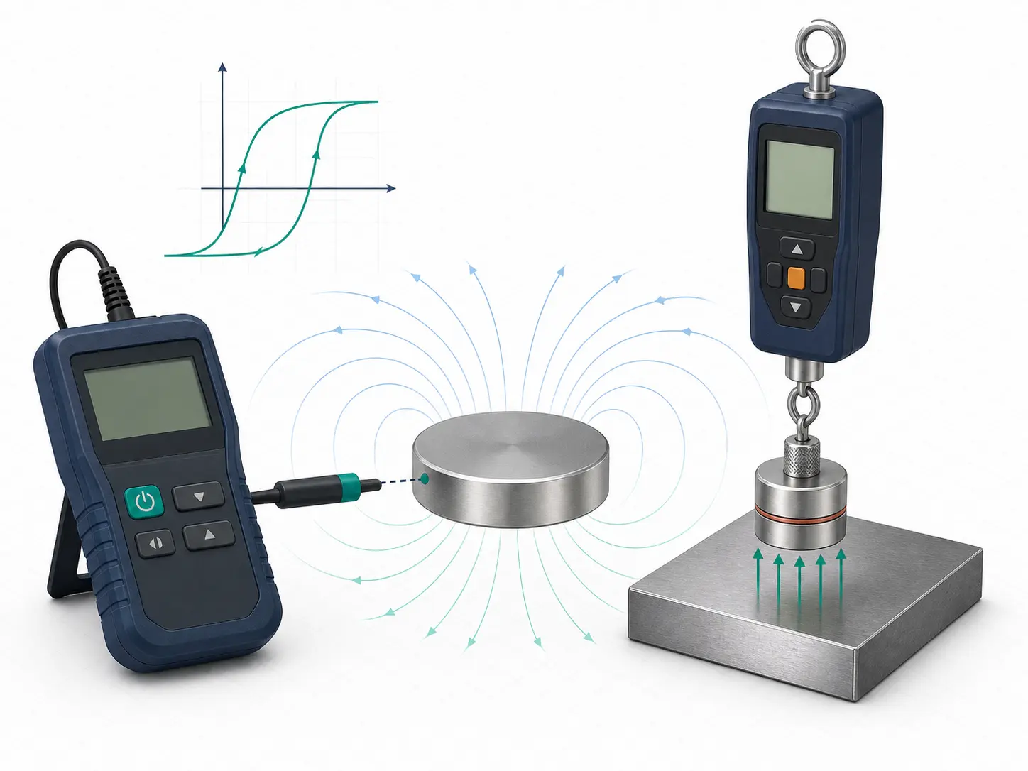
가우스미터는 지정된 위치의 자속 밀도를 측정합니다. 분리력 시험은 통제된 조건에서 자석 또는 자석 어셈블리를 지정된 상대 접촉면에서 분리하는 데 필요한 힘을 측정합니다.
잔류 자속 밀도, 보자력 또는 최대 에너지적과 같은 재료 특성을 검증해야 한다면 히스테리시스 그래프 측정기와 같은 재료 시험 시스템이 더 적합합니다. 모터, 센서, 커플링 또는 유지용 어셈블리의 경우에는 자기장 세기, 토크, 유지력 또는 실제 작동 간극에서의 성능이 더 유용한 결과일 수 있습니다.
“자석의 세기’란 무엇입니까?
자석 세기 측정기를 선정하기 전에 적용 분야에서 중요한 결과가 무엇인지 정의하십시오.
| 알아야 할 사항 | 측정 항목 | 일반적인 장비 | 주요 한계 |
|---|---|---|---|
| 특정 지점의 자기장 | 자속 밀도 | 가우스미터 또는 테슬라미터 | 프로브 위치와 방향에 따라 크게 달라짐 |
| 자기 모멘트 또는 적분 자속 변화량 | 자기 모멘트, 개방 회로 자화 또는 쇄교 자속 변화량 | 적합한 측정 코일을 사용하는 플럭스미터 | 코일 형상, 교정 및 시험 방법에 따라 달라짐 |
| 재료 고유 성능 | Br, HcB, HcJ, BHmax, 감자 곡선 | 히스테리시스그래프 또는 기타 적용 가능한 재료 시험 시스템 | 완성 어셈블리의 성능이 아닌 재료 특성을 시험함 |
| 상대 접촉면으로부터의 분리력 | 이탈력 또는 인장력 | 포스 게이지 및 제어 지그 | 전체 시험 구성에 따라 달라짐 |
| 제품에서의 성능 | 자기장, 힘, 토크, 감지 거리 또는 커플링 출력 | 적용 분야별 시험 지그 | 실제 작동 조건 필요 |
한 범주의 값이 높다고 해서 다른 범주의 결과도 자동으로 더 좋아지는 것은 아닙니다.
예를 들어, 표면 Gauss 측정값이 높다고 해서 특정 인장력이 보장되는 것은 아닙니다. 마찬가지로, 벤치 시험에서 인장력이 높게 측정되었다고 해서 자석이 공극을 통해 필요한 센서 자기장을 형성한다는 의미는 아닙니다.
어떤 자석 세기 시험을 사용해야 합니까?
측정 장비가 아니라 엔지니어링 질문에서 시작하십시오.
| 적용 관련 질문 | 권장 측정 항목 | 필요 정보 |
|---|---|---|
| Hall 센서가 지정된 위치에서 자석을 감지합니까? | 센서 위치에서의 자속 밀도 | 센서 위치, 작동 간극, 자석 방향, 목표 자기장 |
| 자석의 표면 자기장 분포가 일관됩니까? | 지정 좌표에서의 가우스 측정 | 프로브 유형, 측정 그리드, 고정구, 자석 방향 |
| 자석 홀더가 직접 분리 하중을 견딥니까? | 수직 분리력 | 상대 재질, 접촉 면적, 표면 상태, 분리 방향 |
| 어셈블리가 측방향 이동을 견딥니까? | 적용 조건별 전단 또는 미끄럼 시험 | 마찰, 하중 방향, 진동, 표면 상태 |
| 재료가 지정된 자석 등급을 충족합니까? | 통제된 조건에서의 재료 특성 측정 | 요구 특성, 시험편 조건, 적용 시험 방법 |
| 커플링 또는 로터가 요구 출력을 발휘합니까? | 토크 또는 적용 성능 시험 | 작동 간극, 극 배열, 속도, 온도, 정렬 상태 |
| 생산 배치 간 일관성이 유지됩니까? | 합의된 수입검사 또는 생산검사 | 합격 판정 기준, 샘플링 계획, 시험 지그, 보고 방법 |
실제 요구사항이 작동 거리에서의 성능인 경우, 표면 측정만으로는 일반적으로 충분하지 않습니다. 측정 지점은 제품에서 중요한 위치와 일치해야 합니다.
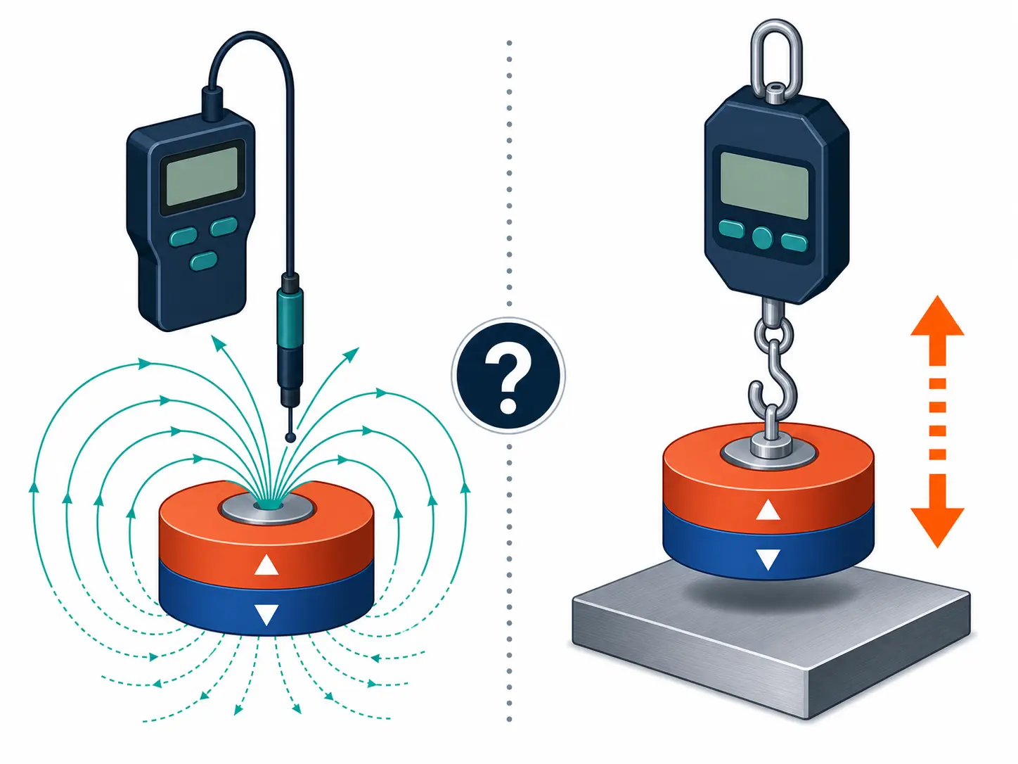
가우스미터로 자석을 어떻게 측정합니까?
가우스미터는 Hall 프로브를 사용하여 프로브의 감지 영역에서 자속 밀도를 측정합니다. 측정 결과는 일반적으로 gauss 또는 tesla로 표시됩니다.
NIST 환산식은 다음과 같습니다.
1 gauss = 0.0001 tesla이며, 10,000 gauss = 1 tesla입니다.
프로브 위치가 중요한 이유
영구자석 주변의 자기장은 균일하지 않습니다. 프로브를 표면에서 멀리 이동하거나 가장자리 쪽으로 옮기거나 기울이거나 다른 자기장 성분 방향으로 돌리면 측정값이 달라질 수 있습니다.
Hall 센서도 프로브 본체 내부에 있습니다. 프로브의 물리적 외부 표면이 항상 정확한 감지면과 일치하는 것은 아닙니다.
Lake Shore의 가우스미터 문서에서는 프로브 정렬, 온도, 영점 조정, 계측기 정확도 및 반복 가능한 위치 결정을 주요 측정 변수로 명시합니다. 또한 자기장 벡터가 Hall 센서에 대해 올바른 방향일 때 최대 응답이 나타난다고 설명합니다.
출처: Lake Shore Model 475 가우스미터 매뉴얼
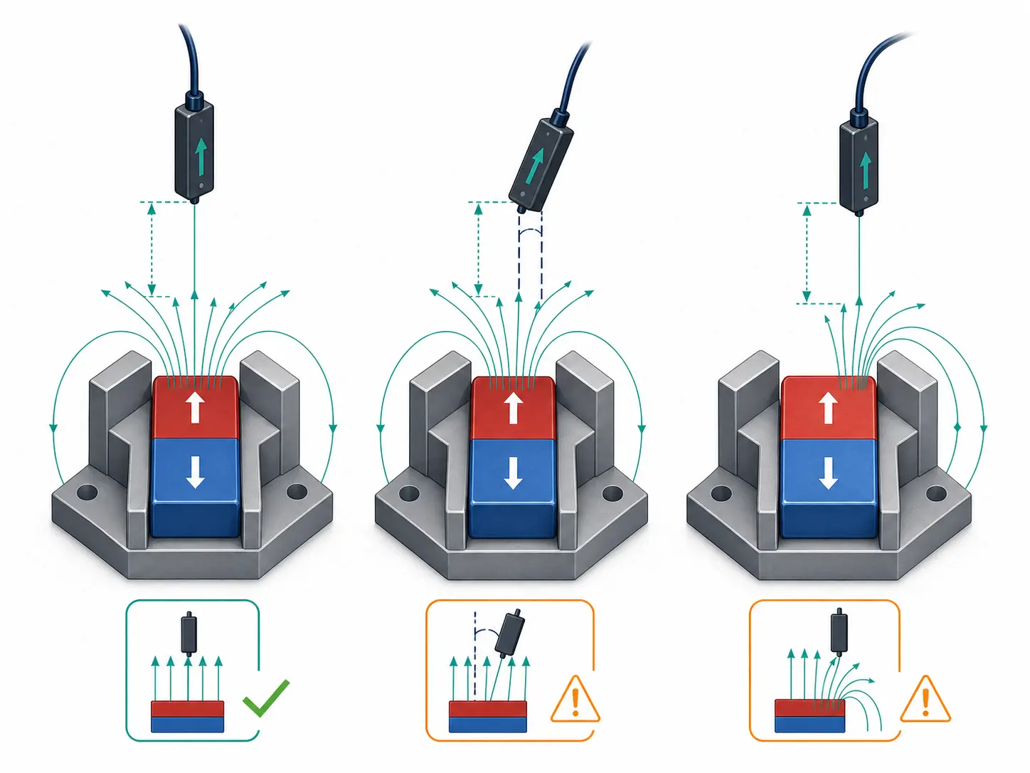
통제된 조건에서의 가우스 측정 절차
이는 일반적인 비교 절차입니다. 계측기 제조업체의 절차와 프로젝트 검사 계획을 우선 적용해야 합니다.
- 자기장 성분과 측정 위치를 정의하십시오.
- 올바른 프로브 유형과 감지 방향을 확인하십시오.
- Allow the instrument and probe to stabilize as required by the manufacturer.
- Zero the probe using the specified method.
- Place the magnet in a repeatable orientation.
- Use a fixture when small position changes could affect the result.
- Position the probe at the defined coordinate and spacing.
- Record the reading without changing the probe angle.
- Repeat the measurement according to the inspection plan.
- Report individual readings, ranges, averages, or pass/fail results as required.
Do not simply move the probe around until the highest number appears unless the stated purpose is specifically to locate the maximum field.
가우스 측정 기록에는 어떤 항목을 포함해야 합니까?
Record at least:
- Magnet drawing or part identification.
- 착자 방향.
- Pole being measured.
- Probe type and sensing direction.
- Measurement coordinate.
- Probe-to-part spacing.
- Part and probe orientation.
- Instrument range and unit.
- Zeroing method.
- Test temperature when relevant.
- Number of measurements.
- Individual values and acceptance range.
Without this information, two suppliers may report different Gauss values even when testing similar magnets.
분리력 시험은 어떻게 수행합니까?
A pull force test measures the force required to separate a magnet or magnetic assembly from a mating surface.
The result is meaningful only when the test conditions are defined. Steel material, steel thickness, surface finish, contact area, fixture alignment, air gap, loading direction, and test speed can all affect the result.
ASTM work item WK70439 is developing a proposed method for pull testing permanent magnet assemblies. It remains a proposed work item rather than a published ASTM standard. ASTM notes that proprietary testing methods can produce widely different values.
출처: ASTM Magnet Pull Force Measurement
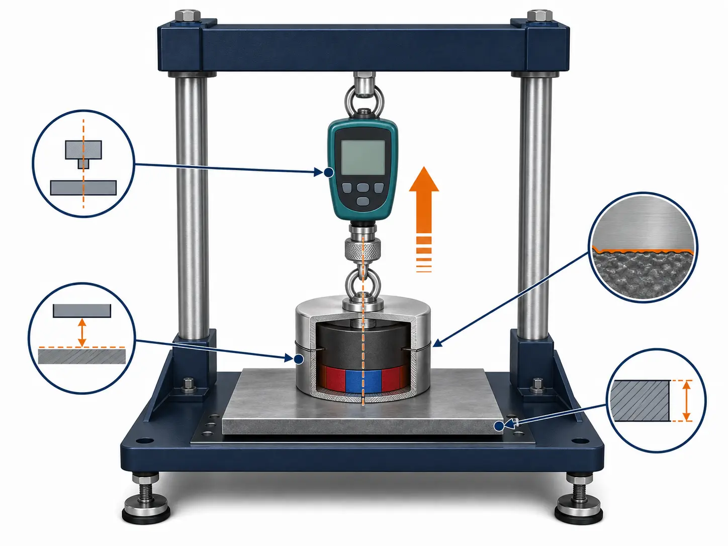
통제된 조건에서의 분리력 비교 절차
The following workflow supports repeatable comparison. It is not a universal standard procedure.
- Identify whether the test applies to a bare magnet or complete assembly.
- Define the mating plate material, thickness, dimensions, and surface condition.
- Clean and inspect the contact surfaces.
- Control any coating, spacer, adhesive layer, or intentional air gap.
- Align the magnet and force gauge with the specified pull direction.
- Apply the load through a controlled fixture.
- Separate the magnet using the agreed test motion.
- Record the maximum force using the agreed reporting method.
- Repeat the test as required.
- Report the fixture and test conditions with the result.
A result that states only “50 kg pull force” is incomplete. It should identify whether the value means kilogram-force, how the assembly was tested, and which mating surface was used.
Force should preferably be stated in newtons. If kilogram-force is also used, the unit should be written clearly rather than shortened to kilograms, which is a unit of mass.
분리력과 전단력은 같습니까?
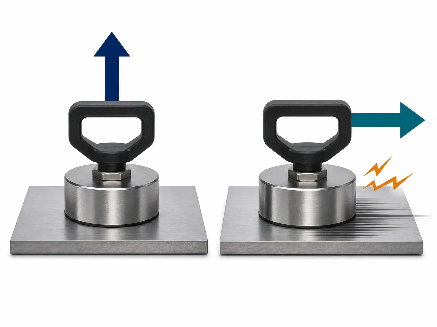
No. A normal pull test separates the magnet perpendicular to the mating surface. A shear or sliding load acts parallel to the surface.
Sliding resistance is affected by friction, surface texture, rubber coatings, mechanical stops, vibration, and load direction. A normal pull-force result should not be used as a shear rating without an application-specific evaluation.
정격 분리력과 안전 사용 하중은 같습니까?
No. A bench pull-force result should not automatically be treated as the safe working load of the final product.
Real applications may introduce:
- Air gaps.
- Thin or low-permeability mating materials.
- Curved or uneven surfaces.
- Shear loading.
- Shock or vibration.
- Temperature changes.
- Misalignment.
- Adhesive or housing failure.
- Magnet chipping or breakage.
The responsible product engineer should establish the required design margin for the actual application. This article does not provide a universal safety factor.
분리력 시험 안전 수칙
Strong magnets can move suddenly, trap fingers, or chip when they strike a fixture or mating plate.
Use a guarded test setup, keep hands outside the attraction path, and follow the workplace risk assessment and PPE requirements. This article is not a complete laboratory safety procedure.
An NdFeB safety data sheet should also be consulted for the specific magnet material and handling conditions.
가우스미터로 자석 등급을 확인할 수 있습니까?
A surface Gauss reading cannot by itself confirm that a finished magnet is N42, N52, or another grade.
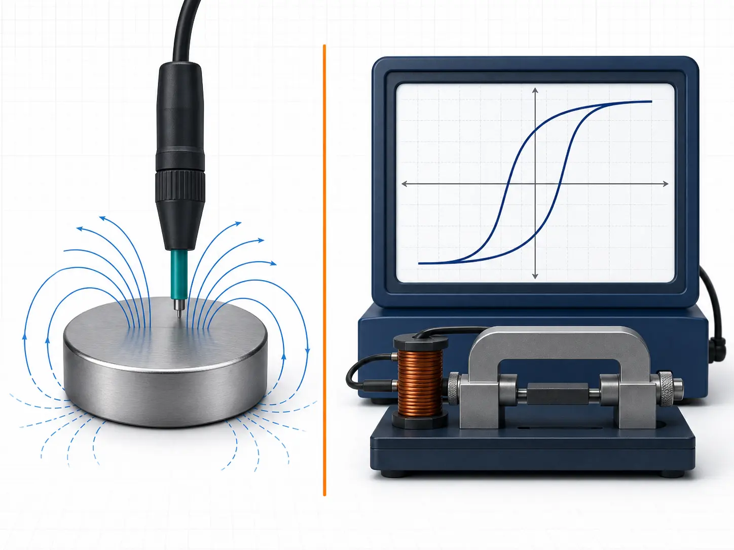
A grade relates to controlled material properties obtained from a magnetization or demagnetization curve. Important properties may include:
- Br: Remanent magnetic flux density after the magnetizing field is removed.
- HcB: Coercive field strength associated with magnetic flux density.
- HcJ: Intrinsic coercive field strength associated with magnetic polarization.
- BHmax: Maximum energy product derived from the demagnetization curve.
IEC 60404-5:2015 defines measurement methods for magnetic flux density, magnetic polarization, magnetic field strength, demagnetization curves, and recoil lines of permanent magnet materials.
출처: IEC 60404-5:2015
ASTM A977/A977M addresses the measurement of high-coercivity permanent magnet materials using hysteresigraphs. It applies to material-property measurement, not simple finished-part surface-field inspection.
출처: ASTM Committee A06.01 Standards
A finished magnet’s Gauss reading is also affected by:
- Magnet dimensions.
- Shape and length-to-diameter ratio.
- Magnetization state.
- 착자 방향.
- Probe position.
- Edge effects.
- Nearby steel or magnetic components.
- Air gap.
Surface-field testing can be useful for comparing finished parts under the same controlled conditions. It should not replace applicable grade documentation or controlled material-property testing.
Readers evaluating a specific high-grade requirement can also review Osenc’s confirmed N52 neodymium magnet page, while keeping in mind that final grade selection still depends on the application.
가우스 값을 인장력으로 직접 환산할 수 있습니까?
No universal formula converts a single Gauss reading directly into pull force.
The two quantities can be related within a fully defined magnetic system, but a valid force prediction also needs information about:
- Magnet dimensions and shape.
- Grade and magnetization state.
- Pole area and pole layout.
- Mating material.
- Steel thickness.
- Working air gap.
- Coatings or spacers.
- Contact geometry.
- Pull direction.
- Nearby magnetic components.
For example, two magnets may show similar field readings at one probe location but produce different pull-force results because their pole areas, thicknesses, or magnetic circuits are different.
The reverse is also possible. Two assemblies may produce similar direct-contact pull force but very different field levels at a sensor positioned several millimeters away.
Use Gauss testing when the field at a location matters. Use pull-force testing when controlled separation force matters.
자석 단품을 시험해야 합니까, 최종 어셈블리 상태에서 시험해야 합니까?
Test the object that best represents the engineering requirement.
| Test object | Suitable when | 주요 한계 |
|---|---|---|
| Bare magnet | Checking polarity, surface-field consistency, or incoming part variation | Does not include housing, steel, adhesive, or working gap |
| Partially assembled component | Checking how a cup, back iron, housing, or carrier changes performance | May not represent the final mounting condition |
| Final magnetic assembly | Verifying actual holding, sensing, torque, or coupling performance | Requires a controlled application-specific fixture |
| Final product | Validating real system operation | Harder to isolate the cause of a failed result |
Nearby steel can redirect magnetic flux. A housing can change the working gap. Adhesive thickness, coating, and assembly tolerance can also change the distance between the magnet and the mating component.
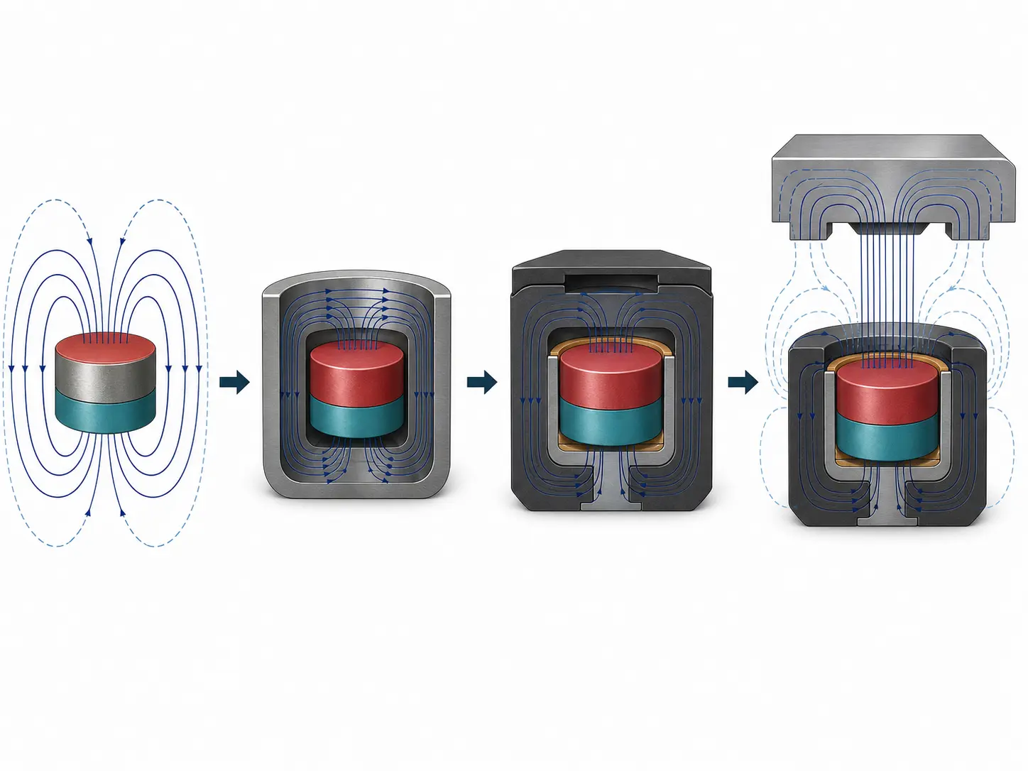
For a sensor or encoder, measure the field at the sensor’s installed position. For a magnetic holder, test against the intended mating material and surface condition. For a coupling or rotor, use the actual working gap and alignment conditions where practical.
Magnetic simulation can help predict field, force, torque, or pole-layout behavior before samples are produced. However, a simulation is a design prediction, not a measured result.
A practical development path is:
- Define the operating condition.
- Model or estimate performance where useful.
- Build a representative sample.
- Validate the magnet or assembly under controlled conditions.
Osenc can support custom magnet and magnetic assembly discussions from drawings, samples, sketches, and application requirements. Available project support may include magnetic-field evaluation, simulation, assembly review, and testing, subject to the project requirements and manufacturing review.
공급업체별 자석 시험 성적서를 어떻게 비교해야 합니까?
Do not compare headline numbers until you confirm that both suppliers used equivalent test conditions.
| Report item | What to check |
|---|---|
| Test object | Bare magnet, subassembly, or final assembly |
| 측정 항목 | Surface field, field at distance, magnetic moment, pull force, torque, or material property |
| Instrument | Equipment type, probe or sensor, range, and unit |
| Test position | Exact coordinate, distance, and orientation |
| Fixture | Mating plate, pull fixture, coil, holder, or assembly condition |
| 환경 조건 | Temperature and other relevant conditions |
| Repetition | Number of tests and whether individual results are shown |
| Result format | Individual values, average, minimum, maximum, or range |
| 합격 판정 기준 | Nominal value, tolerance, minimum value, or pass/fail limit |
| Calibration | Calibration status or traceability required by the purchasing agreement |
A report should allow another qualified person to understand what was measured and, where practical, reproduce the comparison.
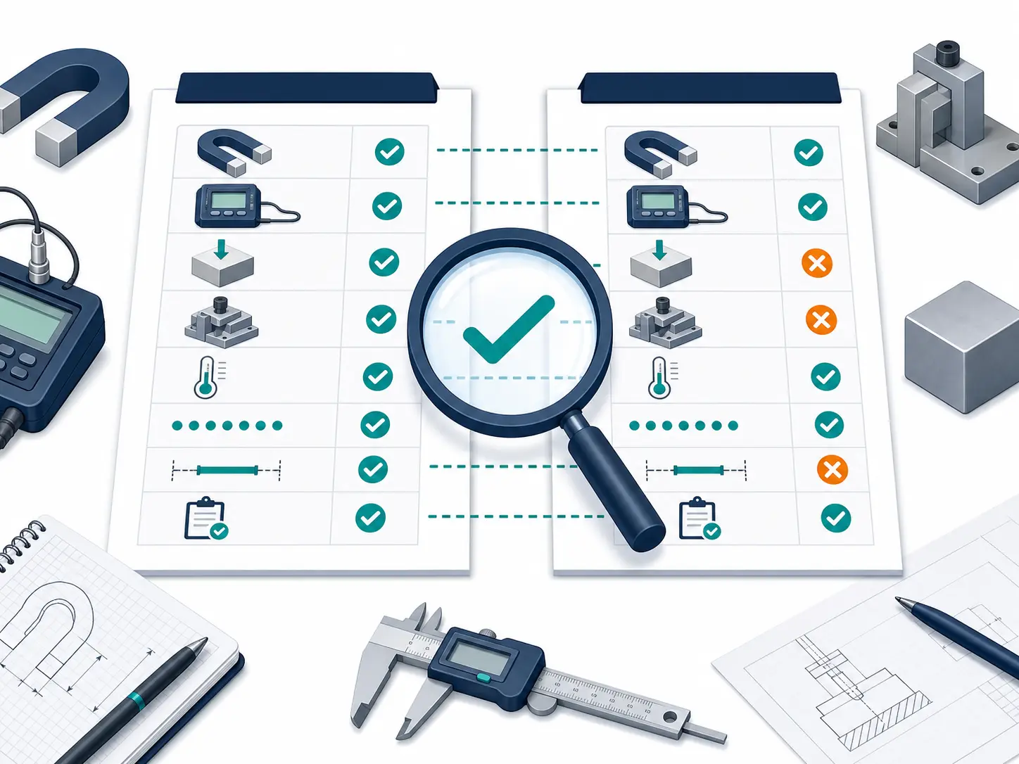
A company quality-management page can show the supplier’s general inspection approach, but it does not replace a project-specific test method or acceptance record. See Osenc’s quality management information for the currently confirmed general scope.
자석 세기 관련 견적 요청서에는 어떤 정보를 포함해야 합니까?
A useful RFQ should describe the required function before specifying a measurement value.
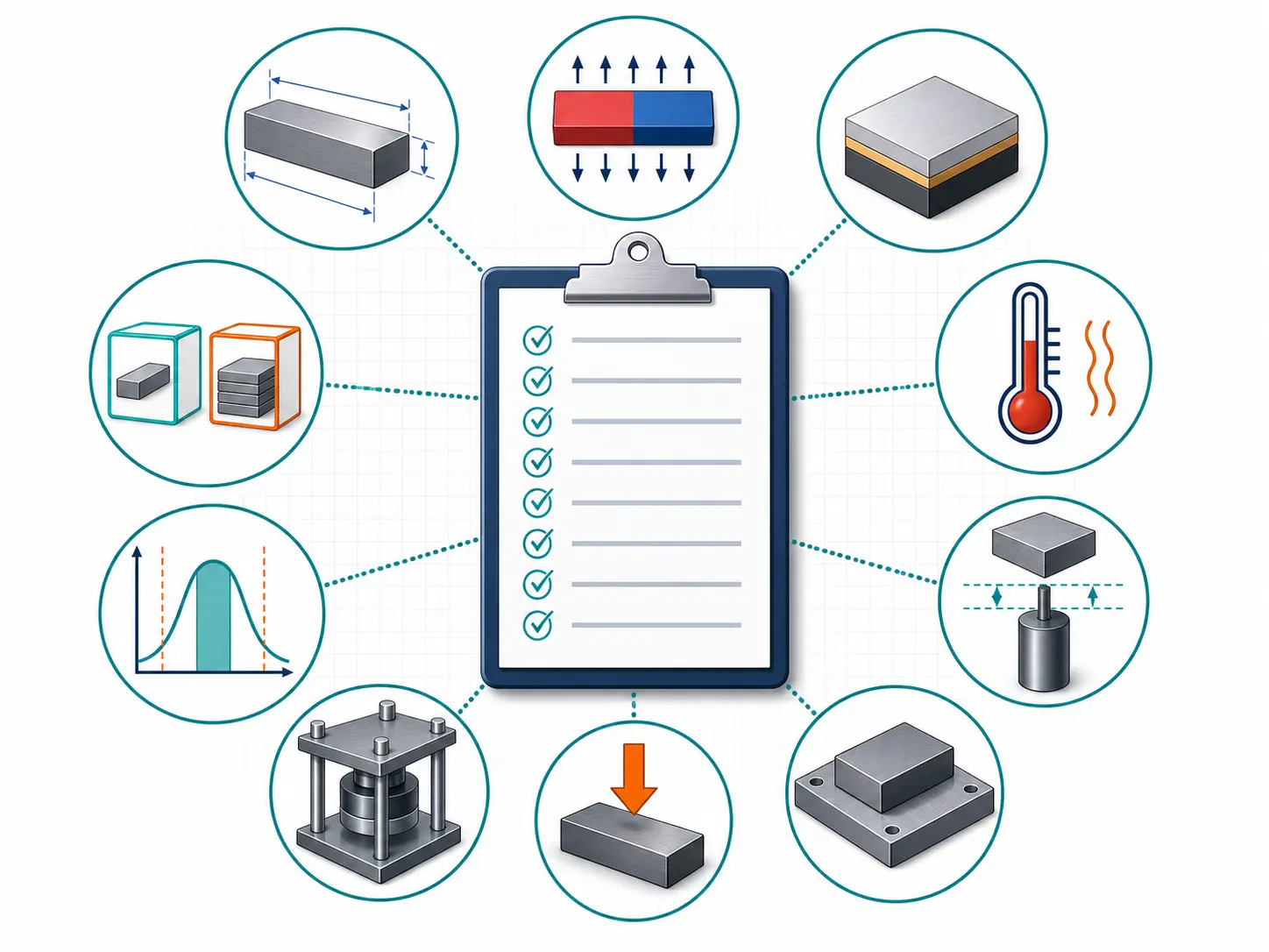
자석 또는 어셈블리 정보
Provide:
- Drawing and revision.
- Dimensions and tolerances.
- Magnet material or proposed grade.
- Magnetization direction and pole layout.
- 코팅.
- Housing, steel parts, adhesive, and other assembly components.
- Intended operating temperature.
- Environmental conditions where relevant.
적용 요구사항
State whether the magnet must provide:
- Holding force.
- Field at a sensor.
- Detection distance.
- Torque.
- Coupling output.
- Positioning force.
- Separation performance.
- Batch-to-batch consistency.
시험 조건
Define:
- Bare magnet or final assembly.
- 측정 위치.
- Working gap.
- Probe direction.
- Mating material and thickness.
- Pull or load direction.
- Fixture requirements.
- Test temperature.
- Required number of measurements.
합격 기준
Specify:
- Target value.
- Minimum or allowable range.
- Unit.
- Sampling requirement.
- Whether individual readings are required.
- Whether the requirement applies to samples, production parts, or both.
A well-defined RFQ reduces the risk of receiving a technically correct test report that does not answer the actual application question.
자주 묻는 질문
가우스 미터와 자석 강도 측정기는 같은 장비인가요?
A gauss meter is one type of magnet strength tester, but the phrase “magnet strength tester” is not specific.
It may refer to a gauss meter, teslameter, pull-force tester, fluxmeter, hysteresigraph, torque fixture, or an application-specific test system. Confirm which magnetic quantity the equipment measures.
스마트폰으로 자석의 세기를 측정할 수 있습니까?
A smartphone may show changes in ambient magnetic field if it contains a magnetometer. Android documents that compatible sensors report magnetic-field components on the X, Y, and Z axes in microtesla.
However, the sensor range, calibration, location, device interference, and repeatability may be unsuitable for magnet acceptance testing.
출처: Android SensorEvent Documentation
Use a phone only for rough indication. Do not treat it as a calibrated gauss meter or supplier acceptance tool.
자석의 자기 성능은 얼마나 자주 시험해야 합니까?
There is no universal testing frequency for every magnet project.
The inspection plan should reflect:
- Application risk.
- Production stability.
- Customer requirements.
- Sample size.
- Process changes.
- Supplier changes.
- The agreed acceptance method.
Critical projects may require different controls from non-critical commercial applications.
자석 시험 요구사항을 정의하는 데 도움이 필요하십니까?
Send Osenc your drawing, working gap, target field or pull force, mating material, temperature range, and proposed acceptance method.
The purpose of the review is to identify what should be measured before sample validation, helping reduce unclear specifications and unnecessary sample revisions.
Discuss a project through the Osenc custom neodymium magnet service 또는 contact Osenc.