





자석의 N극과 S극을 확인하려면 자석의 한쪽 끝이나 한 면 가까이에 나침반을 놓으십시오. 나침반 바늘에서 N으로 표시된 끝이 해당 표면을 향하면 시험한 표면은 자석의 S극입니다. N으로 표시된 끝이 반대 방향을 향하면 시험한 표면은 N극입니다.
이는 서로 다른 자극은 끌어당기고 같은 자극은 밀어내기 때문입니다. 다만 생산 검사, 다극 자석 또는 자석 어셈블리의 경우에는 나침반만으로 충분한 정보를 얻기 어려울 수 있습니다.
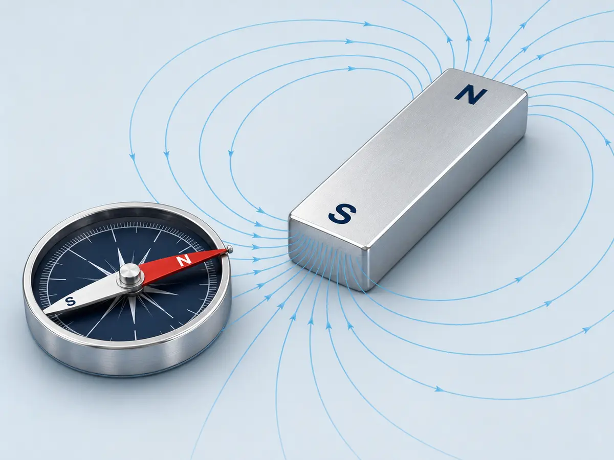
빠른 답변: 어느 쪽이 N극이고 S극입니까?
| 자석 근처에서 나침반의 반응 | 시험 중인 자석의 극 |
|---|---|
| 나침반의 N 표시 끝이 자석 쪽을 가리킴 | 남극 |
| 나침반의 N 표시 끝이 자석 반대쪽을 가리킴 | 북극 |
| 바늘이 옆으로 돌아가거나 결과가 불안정함 | 나침반 위치를 조정하고 주변의 자기 간섭을 제거하십시오 |
| 동일한 표면 내에서 방향이 달라짐 | 자석이 다극 또는 더 복잡한 착자 패턴일 수 있음 |
확인하려는 자극면의 가장자리가 아닌 중앙 부근에서 시험하십시오. 가장자리 부근에서는 자력선이 휘어 나침반 바늘이 옆으로 돌아갈 수 있습니다.
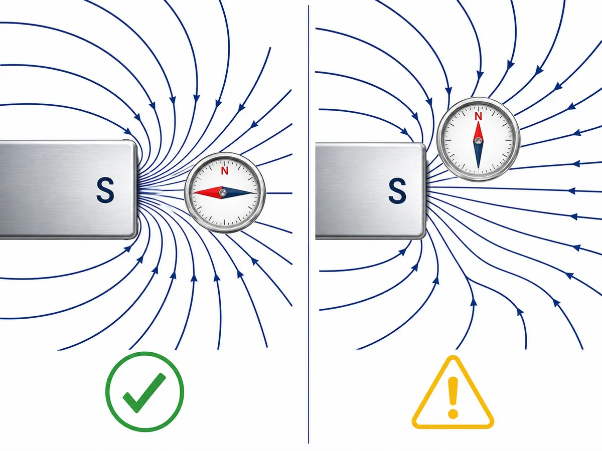
나침반으로 자석의 극성을 식별할 수 있는 이유는 무엇입니까?
나침반 바늘 자체가 작은 자석입니다. 북쪽을 가리키는 끝은 일반적으로 N, 빨간색 또는 화살표로 표시됩니다.
N 표시 끝은 자석의 남극에 끌리고 북극에서는 밀려납니다. 이는 서로 다른 극끼리는 끌어당기고 같은 극끼리는 밀어내는 기본 원리와 같습니다. 자세한 설명: OpenStax 물리학.
용어가 혼동을 일으킬 수 있습니다. 나침반에서 북쪽을 가리키는 극은 대략 지리적 북쪽을 향합니다. 단순한 자극 명명법으로 보면 지리적 북쪽 인근은 자석의 S극처럼 작용하지만, 지리학에서는 일반적으로 북자극이라고 부릅니다. 이러한 명칭의 차이는 영국 물리학회 에서 설명합니다.
자극을 양전하와 음전하로 표현해서는 안 됩니다. N극과 S극은 전하가 아니라 자석의 극성을 나타냅니다.
나침반으로 자석을 테스트하는 방법
일반적인 2극 자석은 다음 순서로 테스트하십시오.
- 다른 자석, 강철 공구, 모터, 스피커 및 전원이 공급되는 전기 장비를 테스트 구역에서 치우십시오.
- 나침반을 안정적인 비자성 표면에 놓으십시오.
- 나침반 바늘이 안정될 때까지 기다리십시오.
- 자석의 한쪽 끝이나 면을 나침반 쪽으로 천천히 가져가십시오.
- 나침반 바늘이 자유롭게 회전할 수 있도록 자석과 충분한 거리를 유지하십시오.
- 나침반에서 N으로 표시된 쪽을 관찰하십시오.
- 반대쪽 끝이나 면에서도 테스트를 반복하십시오.
- 적용 시 방향을 영구적으로 관리해야 하는 경우, 확인한 자극을 즉시 표시하십시오.
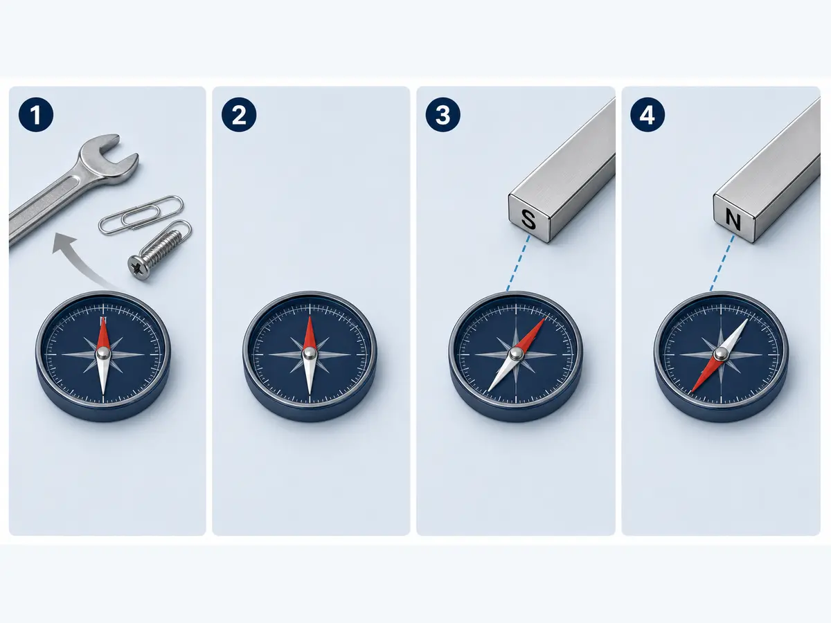
N 표시 끝이 시험 대상 표면을 향하면 해당 표면은 남극입니다. 반대로 멀어지는 방향으로 돌아서면 해당 표면은 북극입니다.
양쪽 면을 모두 검사하면 결과를 교차 확인하는 데 유용합니다. 일반적인 축 방향으로 착자된 원판 자석, 한쪽 평면은 북극으로, 반대쪽 평면은 남극으로 작동해야 합니다.
나침반 결과가 명확하지 않다면?
| 문제 | 가능한 원인 | 조치 |
|---|---|---|
| 바늘이 급격히 튀며 안정되지 않음 | 자석이 너무 가깝거나 자력이 너무 강함 | 거리를 늘리십시오. |
| 바늘이 옆으로 움직임 | 자기장이 휘어지는 가장자리 근처에 나침반이 있음 | 극 표면 중앙 부근에서 테스트하십시오. |
| 나침반을 표면 위로 이동하면 방향이 바뀜 | 다극 착자일 가능성 | 적절한 극 검출기 또는 제어된 자기장 매핑 방법을 사용하십시오. |
| 위치에 따라 바늘이 다르게 반응함 | 주변의 강철, 자석 또는 전기 장비 | 테스트 영역을 정리한 후 다시 테스트하십시오. |
| 양쪽에서 유사한 결과가 나타남 | 테스트 방향 또는 극 위치가 잘못되었을 수 있음 | 착자 도면과 테스트 형상을 다시 확인하십시오. |
나침반은 북극과 남극이 각각 하나씩 있는 단순한 막대형, 블록형, 디스크형 또는 원통형 자석에 가장 유용합니다. 서로 가까이 배치된 다극 자석과 완성된 자석 어셈블리에는 적합성이 떨어집니다.
자석의 극을 식별할 수 있는 다른 방법
극성이 확인된 자석 사용
검증된 기준 자석을 사용하면 다른 자석의 극성을 식별할 수 있습니다.
극성이 확인된 기준 자석의 북극을 테스트할 표면 쪽으로 가까이 가져가십시오:
- 자석이 서로 밀어내면 테스트한 표면도 북극입니다.
- 자석이 서로 끌어당기고 테스트 대상 부품이 이미 자석임이 확인된 경우, 테스트한 표면은 남극일 가능성이 높습니다.
반발이 더 명확한 결과인 이유는 자화되지 않은 강자성 강재도 영구자석의 어느 극에나 끌릴 수 있기 때문입니다. 따라서 흡인만으로는 미지의 금속 부품이 특정 자극을 갖는다는 사실을 입증할 수 없습니다.
전자식 자극 식별기 사용
전자식 자극 식별기는 자석 표면 가까이에 대면 N 또는 S를 표시할 수 있습니다. 단순한 자석을 여러 개 확인할 때 나침반보다 빠르게 사용할 수 있습니다.
단, 감지 거리, 표시 방식 및 적합한 자계 범위는 장치에 따라 다릅니다. 입고 검사 또는 생산 검사에 사용하기 전에 검출기를 극성이 알려진 기준 자극과 대조 확인하고 해당 장치의 설명서를 따르십시오.
극 간격이 좁은 경우, 센서 영역이 필요한 극 패턴을 구분할 수 있을 만큼 작은지 확인하십시오.
가우스 미터 또는 홀 프로브 사용
가우스 미터는 프로브 위치에서의 자속 밀도를 측정합니다. 부호가 있는 측정값은 자기장 방향을 나타낼 수도 있지만, 다음 사항을 알고 있는 경우에만 가능합니다:
- 프로브의 감지 방향.
- 기기의 부호 표기 규칙.
- 프로브의 방향.
- 측정 위치.
- 자석과의 거리 또는 공기 간극.
- 영점 조정 및 기능 점검 절차.
양(+)의 측정값이 항상 북극을 의미하거나 음(-)의 측정값이 항상 남극을 의미한다고 가정하지 마십시오. 결과는 제조업체가 프로브의 양(+)의 감지 방향을 어떻게 정의하는지에 따라 달라집니다.
A gauss meter is more useful than a compass when the buyer must verify both field direction and a specified magnetic-field value. The test conditions must be defined if the reading is used for acceptance.
Can You Use a Smartphone?
A smartphone magnetometer can demonstrate changes in magnetic-field strength and direction, but phone sensors, coordinate systems and apps vary.
It may be useful for a basic experiment, but it should not be the sole method for production inspection, batch acceptance or a safety-related assembly decision.
Can You Suspend the Magnet Freely?
A lightweight bar magnet suspended so that it can rotate freely will normally align approximately with Earth’s magnetic field. The end pointing toward geographic north is called the north-seeking pole.
This method is simple but sensitive to nearby metal, other magnets, air movement and suspension friction. It is better suited to demonstration than controlled inspection.
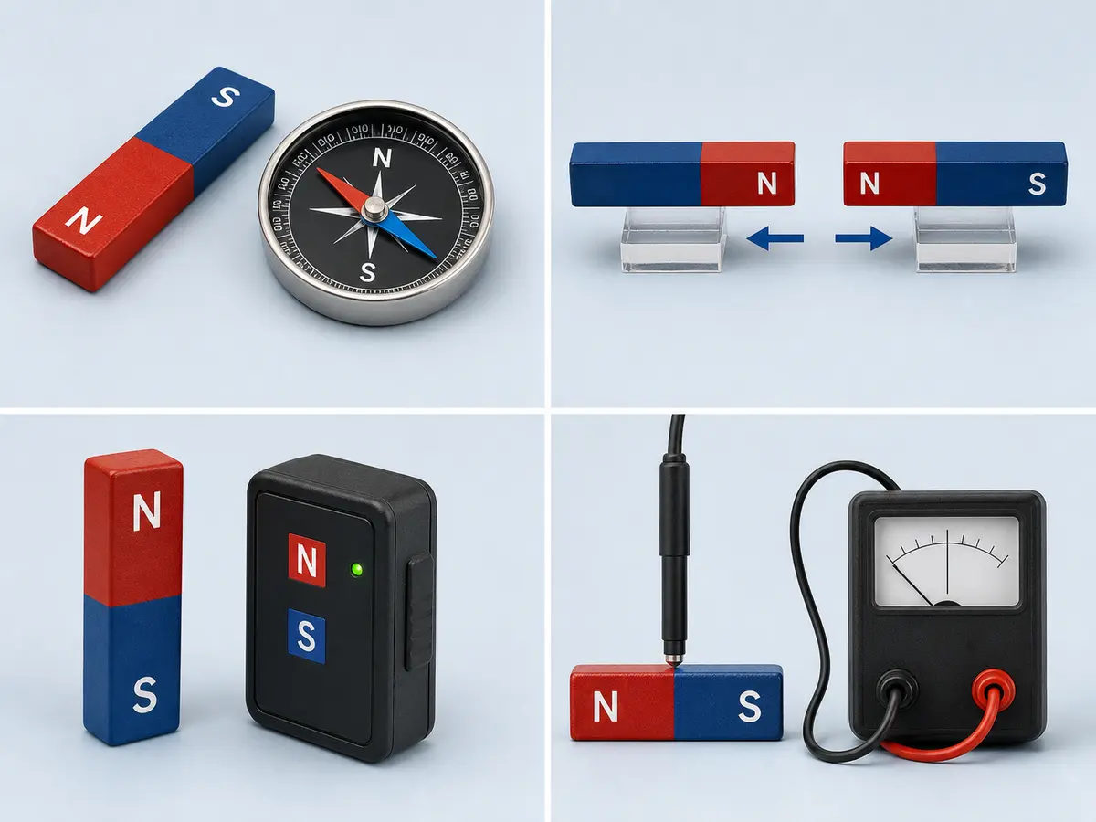
Which Methods Do Not Reliably Identify North and South?
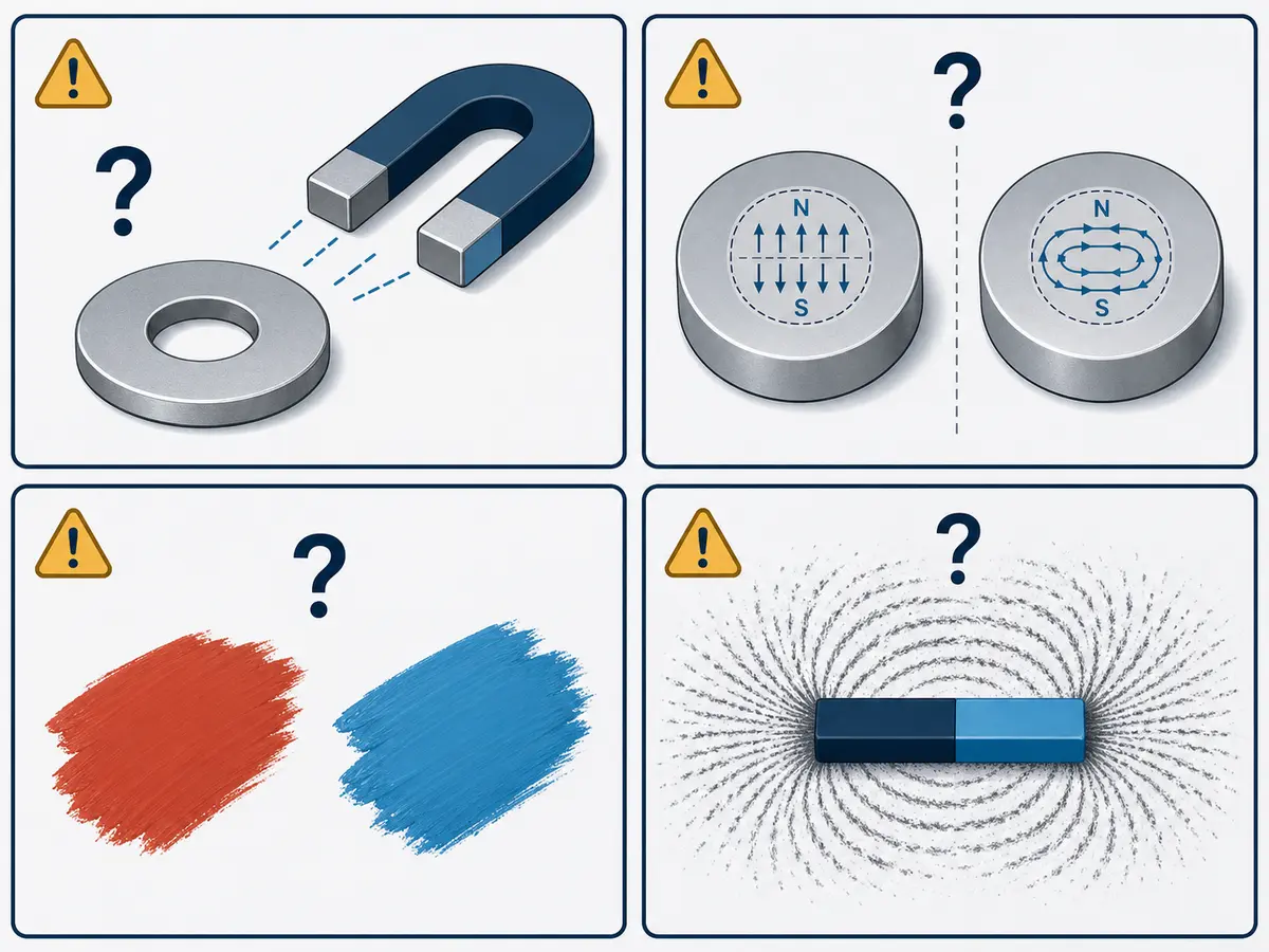
Steel Attraction
A steel object may be attracted to either pole. It cannot tell you whether the tested surface is north or south.
Magnet Color
Red and blue paint are common educational conventions, but there is no universal rule that every red end is north or every blue end is south.
Plating color also does not indicate magnet polarity. Nickel, zinc, epoxy and other coatings are selected for protection or application requirements, not as a universal pole code.
자석 형상
The shape of a magnet does not prove its magnetization direction. Two disc magnets with the same dimensions may be magnetized axially, diametrically or in a custom multipole pattern.
Always confirm the magnetization direction separately.
Iron Filings and Magnetic Viewing Film
Iron filings can show the general magnetic-field pattern, but they do not label a region as north or south.
Standard magnetic viewing film can help reveal pole boundaries and field patterns, but it should not automatically be treated as an N/S identifier. Some specialized indicator products operate differently, so their documentation must be checked.
How Does Magnetization Direction Affect Pole Location?
Pole location depends on magnetization direction, not only on the magnet’s physical shape.
| Magnetization pattern | Typical pole location | 주요 제한 사항 |
|---|---|---|
| 축 방향 | Opposite flat faces | Common for discs, rings and cylinders, but the drawing must still confirm it. |
| 직경 방향 | Opposite sides across the diameter | Common for some cylinders, sensor magnets and rotors. |
| 방사 방향 | In some designs, inner and outer circumferences | Segmented and multipole rings may use different orientation patterns. |
| Multipole | Alternating pole regions on one or more surfaces | Pole count, pole pitch and sequence require a drawing or field map. |
| Custom magnetic assembly | Determined by the individual magnet layout | The external field may not match the apparent orientation of one visible magnet. |
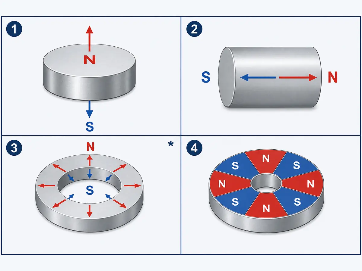
A ring magnet is not automatically radially magnetized. Many ring magnets are axially magnetized, with north and south on the two flat annular faces.
For 맞춤형 네오디뮴 자석에 사용하면, the drawing should specify the magnetization direction rather than relying on shape names such as disc, ring or block.
Why Does Magnet Polarity Matter in an Assembly?
For a magnet simply attracting an unmagnetized steel plate, north versus south may not affect the basic holding function.
Polarity becomes important when the magnet interacts with:
- Another permanent magnet.
- A Hall sensor or magnetic encoder.
- A motor rotor or stator.
- A magnetic coupling.
- A multipole ring.
- A Halbach array.
- A polarity-sensitive detection system.
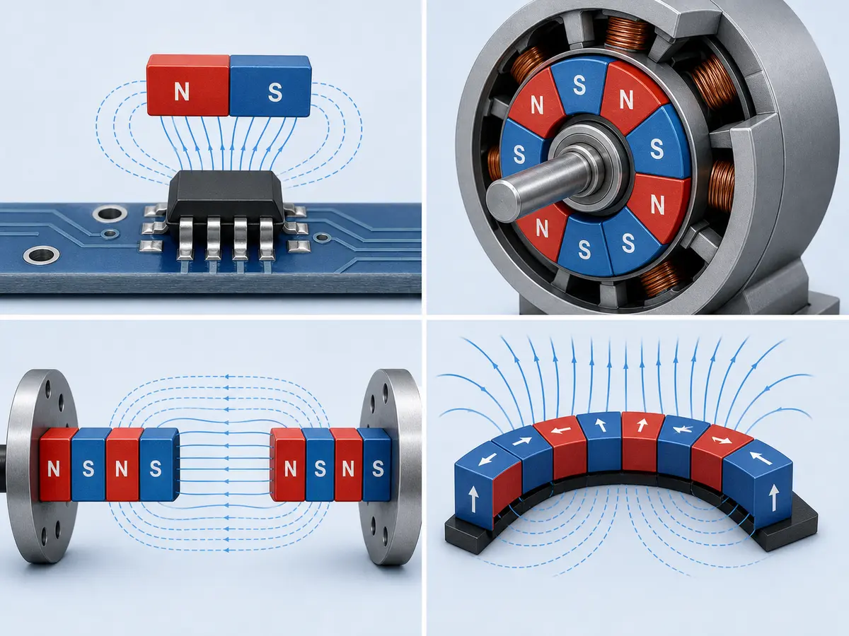
Installing one magnet in the wrong direction can change attraction into repulsion, reverse a sensor response or disrupt the intended field pattern.
For these applications, the requirement should not be written only as “magnetized.” The drawing or specification should define the required direction, pole layout and acceptance method.
How Should Buyers Verify Polarity in a Batch?
- Confirm the approved drawing revision.
- Identify whether acceptance concerns N/S identity, pole sequence, field value or functional response.
- Establish a verified master magnet or approved reference.
- Select a detector suitable for the pole size and spacing.
- Define the test position, orientation and distance.
- Use a fixture when repeatable positioning matters.
- Mark or separate inspected parts to prevent mixing.
- Record the results and any nonconforming pieces.
- Use orientation features or mistake-proofing during assembly where possible.
- Complete a functional check when polarity alone does not prove assembly performance.
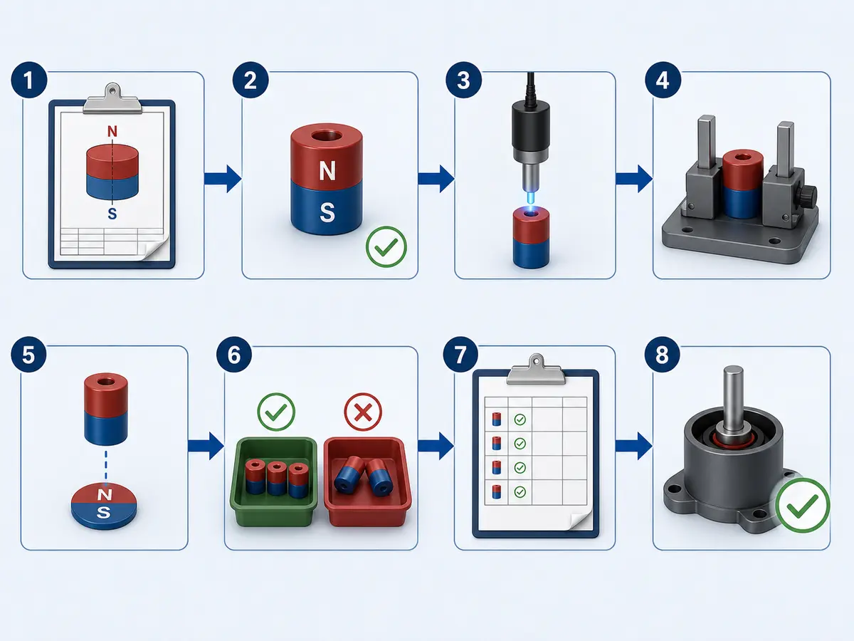
A useful inspection record may include:
- Part number.
- Drawing revision.
- Required pole or pole sequence.
- Test location.
- Fixture orientation.
- Instrument or reference identification.
- Result.
- Date and inspector.
If a magnetic-field value is an acceptance criterion, also define the probe, air gap, measurement direction and permitted range. A documented plan can also support communication with the supplier’s 품질 관리 team.
What Exactly Should the Acceptance Criterion Be?
“Check magnet polarity” may be too vague for a production drawing or purchase order.
Choose the acceptance basis that matches the application:
| Acceptance basis | Suitable when |
|---|---|
| N/S identity only | A simple magnet must be assembled in the correct direction. |
| Pole count and sequence | A multipole ring, rotor or encoder magnet must follow a defined pattern. |
| Magnetic-field reading | A specified field component must be measured at a controlled location and gap. |
| Field map | Pole boundaries or field distribution matter across a surface or working area. |
| Functional response | The magnet must operate correctly with a sensor, motor, coupling or complete assembly. |
A polarity test does not automatically prove that the magnetic field is strong enough for the application. Likewise, one surface-field reading may not prove performance at the actual working gap.
What Information Should Be Included in an RFQ?
For a custom or polarity-sensitive magnet, provide:
- Magnet material and grade, if already selected.
- Complete dimensions and tolerances.
- 착자 방향.
- Number of poles.
- Required pole sequence or pole pitch.
- Pole-marking location.
- Assembly orientation.
- Working distance or air gap.
- Mating magnet, steel component or sensor information.
- Operating temperature.
- Required inspection method.
- Whether acceptance is based on N/S identity, field value, field map or functional response.
- Whether the pole mark must remain visible after assembly.
If the magnetization pattern is difficult to show in words, include a marked drawing, sketch or sample.
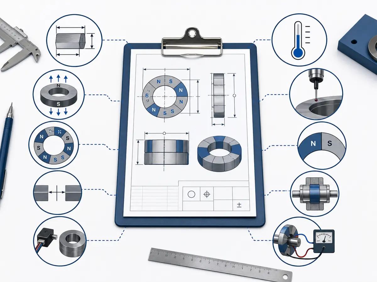
Osenc can review drawings, sketches, samples and application requirements to help clarify the magnetization direction, pole layout and suitable verification method. Magnetic simulation may support design evaluation for complex assemblies, but physical inspection is still needed to confirm actual production parts.
자주 묻는 질문
자석의 빨간색 끝은 항상 N극인가요?
아닙니다. 빨간색과 파란색은 교육용으로 흔히 사용되지만, 보편적인 제조 표준은 아닙니다. 색상에 의존하지 말고 자극을 확인하십시오.
철가루로 어느 쪽이 N극인지 확인할 수 있습니까?
철가루는 자기장 분포를 보여 주지만 어느 영역이 N극인지 S극인지는 구분하지 못합니다.
철제 물체로 자석의 극성을 판별할 수 있습니까?
아니요. 강철은 어느 극에도 끌리므로 N극과 S극을 구분할 수 없습니다.
링 자석의 자극은 어디에 있습니까?
착자 방향에 따라 다릅니다. 축 방향으로 착자된 링 자석은 일반적으로 양쪽 평면에 각각 자극이 형성됩니다. 일부 방사 방향 착자 설계에서는 내주면과 외주면이 서로 반대 극을 이룰 수 있으며, 다극 링에는 극성이 교대로 배열된 여러 자극 영역이 있습니다.
가우스 미터로 N극과 S극을 구분할 수 있습니까?
프로브 방향과 계측기의 부호 규칙을 알고 있으면 자기장 방향을 판별할 수 있습니다. 이러한 조건이 확인되지 않으면 양수 또는 음수만으로 N극/S극을 신뢰성 있게 판단할 수 없습니다.
스마트폰으로 자석의 극을 식별할 수 있습니까?
휴대전화로 자기장의 변화를 확인할 수는 있지만, 센서와 앱마다 특성이 다르므로 신뢰할 수 있는 생산 검사 도구로는 적합하지 않습니다.
자석이 부서지면 각 조각에도 N극과 S극이 있습니까?
네. 일반 영구자석을 파손하면 더 작은 조각으로 나뉘지만, 각 조각은 여전히 N극과 S극을 가진 자석으로 작용합니다. 단독으로 존재하는 자극이 생성되는 것은 아닙니다.
Need Help Confirming a Custom Magnetization Pattern?
For a simple two-pole magnet, a compass or verified reference magnet may be enough. For multipole magnets, rotors, sensor magnets, magnetic couplings or other assemblies, specify the pole pattern and verification method before production.
Osenc can review your drawing, sketch, sample or application requirements to help clarify the magnetization direction and inspection approach.
Discuss Your Magnetization Requirements